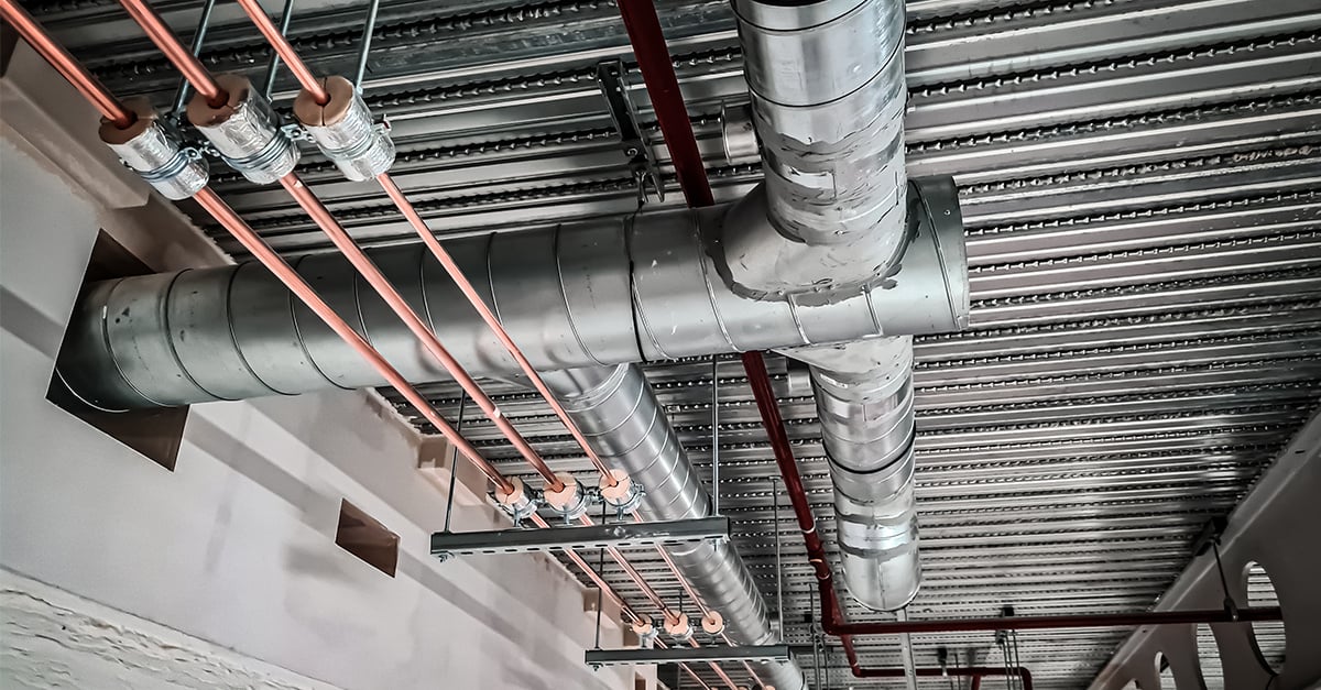
We are leading suppliers to #building services contractors, supplying all those diverse products that fix and support #pipework, #electrical systems and #HVAC.
💡 𝗢𝘃𝗲𝗿-𝗘𝗻𝗴𝗶𝗻𝗲𝗲𝗿𝗶𝗻𝗴 𝘃𝘀 𝗦𝗺𝗮𝗿𝘁 𝗘𝗻𝗴𝗶𝗻𝗲𝗲𝗿𝗶𝗻𝗴: 𝗦𝘁𝗿𝗶𝗸𝗶𝗻𝗴 𝘁𝗵𝗲 𝗥𝗶𝗴𝗵𝘁 𝗕𝗮𝗹𝗮𝗻𝗰𝗲
When it comes to M&E supports, performance is non-negotiable. But more contractors are recognising that bigger doesn’t always mean better.
Over-engineering — adding extra material or safety margins “just in case” — can feel like a safer choice, but in practice it often creates challenges rather than solving them.
Some of the hidden impacts we see include:
🔹 Unnecessary cost – Extra material and complex designs can quickly push budgets higher.
🔹 Heavier assemblies – Increasing the weight makes installation harder and more time-consuming.
🔹 Reduced flexibility – Bulky brackets can take up valuable space in already congested service zones.
🔹 Concentrated stress – Too much rigidity can create points of weakness instead of resilience.
🔹 Higher environmental footprint – Using more steel than needed adds carbon without adding value.
A better approach is smart engineering.
✅ Tested channel systems provide proven load data, so supports can be right-sized with confidence.
✅ Well-designed brackets strike the balance between performance and practicality.
✅ Getting it right first time saves time, reduces waste, and builds reliability into the project from the outset.
The goal isn’t to do more — it’s to do what’s needed, and to do it well. That’s what drives safer, more efficient, and more sustainable outcomes across the supply chain.
💬 How are you approaching the balance between performance and efficiency in your projects?
A support drawing can show the arrangement without explaining the design basis.
That matters when a project-specific M&E support is being used for technical submission, procurement, fabrication or installation.
A drawing may show dimensions, fixing positions, clearances and assembly intent. Those details are useful. They help people see what needs to be built.
But they are not always the same as design evidence.
The stronger check is whether the drawing is connected to the assumptions behind it: the loads allowed for, the building interface, the fixing basis, the level of calculation or validation, the review status, and the point at which a change would need another look.
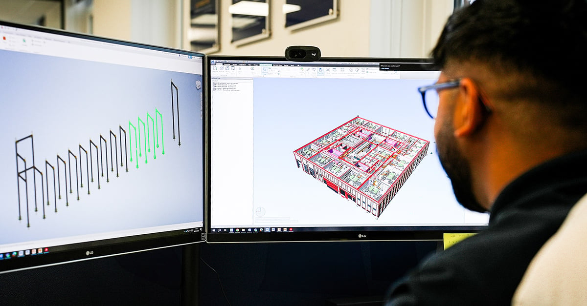
That is where Design, Engineering & Fabrication is useful. It connects the required M&E support arrangement to the engineering checks, drawings and deliverables the job actually needs, whether the scope is design only or design plus fabrication.
Not every support detail needs the same level of engineering. A drawing can be enough when the design basis has already been resolved elsewhere.
But when the drawing is being relied on as part of the evidence pack, it should be clear what evidence it actually carries.
The strongest output is not just a neat drawing.
It is a support arrangement that is drawn, checked and easier to explain when someone asks why it is fit for the job.
Practical installation training earns its value when site conditions stop matching the method.
On M&E support and fixing work, the intended method can be clear at the start: the specified product, correct tool, installation sequence, torque requirement, and the check before the fixing or support is relied on.
The pressure comes when one of those points changes on site.
The supplied product is not the one specified.
The substrate or fixing point is different.
The setting tool is missing.
The support arrangement has changed.
The installation does not behave as the instructions describe.
This is where training needs to connect with supervision.
M&E installers need to know when they can continue, when they should pause, what should be checked, and who needs to be involved before work carries on.
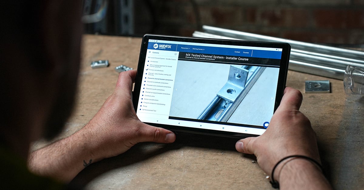
That is the practical value of MIDFIX Academy. It gives installers and supervisors structured training around method, tools, checks and installation discipline, so training can support site supervision rather than sit apart from it.
A certificate is useful evidence that training took place. The stronger outcome is when that learning helps the right question get raised before an unclear condition becomes a loaded installation.
Good training makes the intended method clearer.
It also makes the stop point easier to recognise.
Low-level rooftop access still needs a defined arrangement.
A small pipe run, cable tray or duct crossing may not need a full walkway or large platform. It still needs a planned way for people to move, inspect or maintain around it.
For M&E contractors, the access decision usually sits in the detail:
- what clearance is needed over the service
- whether the route is occasional inspection or regular maintenance
- how the roof membrane is protected
- where the feet or bearing points can sit
- what else is already occupying that roof zone
If those points are left vague, the result is often an improvised step, an awkward path across services, or an access detail that gets revisited late in the job.
This is where low-level access should be treated differently from standard rooftop walkways and larger platforms.
MX-R Access Low Level sits in that space: a modular stepover/access option for smaller rooftop obstructions, where the requirement is defined but does not justify a heavier access arrangement.
The aim is proportionate access: enough structure to make the maintenance route clear, without turning every low obstruction into the same-sized solution.
Define the obstruction, the use, and the roof interface first. The access detail should follow those conditions.
For composite metal deck, the deck profile is part of the fixing evidence.
The fixing is not being selected against load alone. It also depends on the profile it is engaging with, the recess dimensions, the condition of the slot, the manufacturer's method, and whether the deck has been altered before the fixing is loaded.
That matters because composite deck can create a different site problem from a plain concrete soffit.
If the profile has opened up or distorted, tightening harder is not a technical fix. It can damage the fixing and still leave the load basis unclear.
If a fixing is chosen because it is close to the profile rather than matched to it, the product evidence may not apply to the actual installation.
If the deck is drilled through so the services can be fixed into the concrete above, the question is no longer only load capacity. It also becomes a question of whether the deck's intended performance and evidence basis have been changed.
For M&E contractors and supervisors, the useful check is to define the fixing basis before installation is asked to solve the problem. That means confirming the deck profile, the intended fixing, the slot condition, the installation method, the torque requirement, and what needs to be recorded if the intended fixing cannot be used.
A structured fixing decision makes the installation easier to explain later.
It is not about making decking fixings more complicated than they need to be. It is about keeping the selected fixing, the actual deck condition and the retained evidence aligned before the service is hanging from it.
Pre-assembled M&E supports help most when the site interface is already clear.
Moving work away from site can be a good decision. It can reduce hot works on site, make installation more predictable and give M&E contractors a more controlled support package before labour is under pressure.
But pre-assembly cannot remove uncertainty that has not been dealt with.
If the support is being built around assumed dimensions, unconfirmed fixing points, unclear access, unresolved service positions or delivery constraints that have not been checked, the risk does not disappear. It usually comes back as site adjustment, revised drawings, transport problems, or a support that no longer fits the intended arrangement.
That does not mean site assembly is the weaker option.
For some M&E support arrangements, controlled site assembly or modular adjustment is the better fit because the final interface still needs to be confirmed. For others, off-site fabrication or pre-assembly protects the programme because the loads, dimensions, access path, fixing basis and installation sequence are already defined.
The useful decision is not simply:
"Can this be made off site?"
It is:
"Is the information mature enough for off-site work to reduce site risk rather than move it?"
That is where Design, Engineering & Fabrication is most useful. It connects the support design, fabrication method, delivery constraints and installation intent before the package is committed.
Pre-assembly is strongest when it turns known information into a buildable support package.
If the key interfaces are still moving, the better step is to define them before fabrication or installation is asked to absorb the uncertainty.
An approved support design is only as useful as the installed condition it still matches.
On M&E projects, the design pack can be clear and the installation can still shift as the work moves from model to site.
A service run moves to clear another package.
A bracket is adjusted around existing containment.
A fixing point changes because the steel or concrete interface is not where the design information said it would be.
An agreed change is made under programme pressure.
None of that automatically means the installation is wrong.
It does mean the evidence has to be reconciled.
The useful handover question is not only:
"Was there a drawing?"
It is:
"Does the installed arrangement still match the assumptions behind that drawing?"
That check connects the support configuration, applied loads, fixing points, selected system or components, agreed changes and retained records.
When that link is clear, the handover pack becomes more than admin. It explains what was intended, what was installed, what changed and why the final arrangement is easier to explain and defend.
For M&E contractors, that is where tested systems, anchor and fixing records, and design input all earn their keep.
The aim is not to catch people out.
It is to stop a good design becoming a weak record because site reality was never checked back against the evidence.
A bracket configuration output only stays useful while the inputs behind it still match the project.
For repeatable M&E bracketry, speed matters. But the stronger value is not simply that a calculation can be produced quickly. It is that the bracket has been configured from a defined set of information.
The output depends on the service load, tier spacing, bracket dimensions, substrate or fixing basis, channel profile and available space.
If one of those points changes after the output has been created, the report may need checking against the revised condition before it is relied on again.
That is where dynaMX works best: suitable repeatable MX-based bracketry, with defined inputs, drawing output and an engineering technical report behind the configuration.
It gives M&E contractors a faster way to handle repeatable bracket design, while keeping the technical basis visible.
The boundary is important too. If the bracket becomes unusual, heavily variable, mixed-system or different from the configured arrangement, it needs the right technical review before it becomes part of the installation.
When the inputs stay controlled, the output is easier to use and easier to stand behind.
When the inputs change, the useful step is to review the configuration before the bracket reaches site.
The moment a support or fixing is substituted, the evidence route may have changed too.
That does not mean every substitution is wrong.
On M&E projects, changes happen for normal reasons: availability, programme pressure, cost review, access, or a site condition that does not match the original assumption.
The risk comes when the change is treated as a line-item swap, while the evidence behind the original selection is assumed to travel with it.
A different anchor, channel, fitting or support component can affect the product data being relied on, the tested system basis, the connection detail, the installation method, the tools or torque required, and the records needed for handover.
That is why the useful question is not only "does it look equivalent?"
It is:
Does the evidence still apply to the actual arrangement being installed?
If the answer is unclear, the substitution needs technical review before it becomes part of the job.
This is where tested support-system evidence and a clear Anchor Fixings Strategy help. They give M&E contractors a better basis for what was selected, what can change, what needs approval, and what should be retained as a record.
The aim is not to stop procurement or site solving real problems.
It is to make sure a practical change does not become a hidden change to the evidence basis.
The safer substitute is one that has been reviewed, accepted and recorded.
It is a controlled change, not a quiet break in the evidence route.
The anchor decision changes when the substrate is uncertain.
On M&E projects, the drawing or fixing schedule can make the substrate assumption look settled. In practice, the site check may find something less straightforward: concrete strength that is not confirmed, cracked or non-cracked assumptions that need checking, hollow or variable masonry, edge conditions, or a refurbishment substrate that does not match the original assumption.
That uncertainty matters before the work reaches installation.
It can affect which anchor evidence applies, whether the application sits inside the approval basis, what installation method and setting tools are needed, whether testing has to answer an allowable resistance question, and what record needs to be retained.
If those points are handled before selection, the project still has room to make a controlled decision.
If they appear only when the anchor is being installed, the options narrow quickly: swap to something similar, rely on habit, or ask a test to create confidence after the basis has already changed.
That is where a stronger Anchor Fixings Strategy makes practical sense. It treats substrate information as part of the selection process, not as a late reason for reassurance.
The aim is not to make anchor work slower.
It is to make the fixing decision easier to specify, easier to install correctly, and easier to explain when someone asks why that anchor was used in that location.
In a congested corridor or riser, the final support arrangement is only one part of the problem.
The harder part is often the sequence.
Existing trapezes may still be carrying live services. A new busbar or containment route may need to pass through the same zone. Future capacity may need to be allowed for before that phase is installed. Fixing points that looked available in the model may be compromised by steelwork, bracing, access space or other bracketry.
That is a different design problem from a repeatable bracket run with known loads and clear fixing points.
The question is not only whether the final arrangement has capacity. It is whether the arrangement can be installed, adjusted and evidenced without losing control of the loads already in the area.
For project engineers and M&E contractors, that is where the brief needs site reality as well as design intent: existing services, retained loads, fixing restrictions, survey information, installation sequence and the limits of any adjustment.
Project-specific M&E support design earns its keep in those grey areas, where the design has to work with what is already there as much as what is being added.
When that information is captured early, the support package has a clearer basis for review, installation and handover.
Fixings boards are most useful when they make the site decision clearer.
On anchor work, the selection can be right on the technical submission and still become difficult to evidence later if the information does not travel cleanly to the point of installation.
The practical link is simple:
- which fixing has been specified
- where it is being used
- which tool or method applies
- whether any change has been approved
- what record needs to be retained
For M&E contractors, that visibility helps supervisors and installers work from the same basis. It reduces the need to check from memory, guess from similar-looking fixings, or rely on a document that never reaches the people doing the work.
That is why fixing boards and fixing records sit naturally inside a stronger Anchor Fixings Strategy.
They are not there to make the file heavier.
They are there to connect selection, supply, installation, checking and retained evidence, so the finished anchor installation is easier to explain later.
A good fixing board does not replace training, supervision or correct installation method.
It gives supervisors and installers a clearer reference point before the fixing is loaded and before the record is needed.
Rooftop access is easier to get right when it is treated as part of the roof layout.
When access is considered alongside plant, pipework, ductwork and containment, there is more room to make the access detail work well.
Walkways can follow clearer routes.
Stepovers can be positioned around services.
Platforms can be sized around real maintenance needs.
Membrane protection, guarding and assembly can be considered while the layout is still developing.
That gives M&E contractors a more straightforward way to move from roof conditions to a buildable access arrangement.
The inputs are practical:
- who needs to reach the equipment
- what services need to be crossed
- what clearance is needed
- how the roof membrane will be protected
- where guarding, lifting and assembly need to be considered
MX-R Access is designed for planned rooftop access, using modular walkways, stepovers and platforms configured around rooftop services.
That starts with the roof conditions being defined properly. With the right inputs, it gives M&E contractors a clearer way to create an access arrangement that is buildable, adjustable and easier to explain later.
Good rooftop access helps maintenance remain straightforward through the life of the plant.
With a tested channel system, the connection detail is part of the evidence.
The evidence behind an M&E support system is not held by one length of channel in isolation. It depends on the system being selected, assembled and recorded in line with the basis that made the data useful in the first place.
That is why the small installation details matter: specified system components, correct fastener size and grade, channel nuts seated properly, final tightening to the stated torque, and records that show what was installed.
For M&E installers and supervisors, these are not separate admin tasks. They protect the link between the design basis and the support that ends up on site.
They also give project engineers a cleaner way to explain what was selected, installed and checked.
That is where the MX Tested Channel System has its value. It gives M&E contractors a tested and traceable support-system foundation, but that evidence still depends on the installed arrangement matching the intended system and method.
If a connection detail changes, treat it as a technical question before it becomes a site workaround.
For a designed and engineered M&E support, the required configuration is only part of the brief.
The rest is the project information that tells the design what it has to answer.
For M&E contractors, the early questions are practical:
Which service or item of plant is being supported?
What loads, spans and connection points does the configuration need to account for?
Where does the M&E support connect back to the building?
What space, access or lifting constraints affect the arrangement?
What finish or environmental conditions matter?
Is the requirement design and engineering only, or design, engineering and fabrication?
Those details shape the design basis.
They affect the level of calculation required, the proposal, the approval process, the fabrication drawings and the way the M&E support will eventually be installed.
When they are clear early, the design is easier to scope and easier to review.
When they arrive late, the specialist can still help, but the work starts with more assumptions. That usually means more questions, more revisions and more pressure to settle technical details after the practical workaround is already taking shape.
That is where Design, Engineering & Fabrication is strongest.
Its value is not generic fabrication capacity. It is the ability to turn a project-specific M&E support requirement into a buildable, documented answer, within a defined scope.
The earlier the brief is made specific, the easier it is for everyone to understand what is being designed, what is being supplied and what still depends on the project conditions.
On above-ground pipework, adjustment works best when it is planned into the support system from the start.
Drawings, plinth levels and pipe positions do not always land exactly as expected once the installation reaches site.
That does not make adjustment a problem in itself.
The problem is when adjustment becomes unmanaged rework: cutting, welding, sending supports away for modification, using temporary supports, or asking installers to make a detail work without a clear basis.
For contractors installing above-ground pipework, the useful planning check is simple: where movement is likely, which parts can be adjusted, and what still needs confirming before the support is loaded.
That is where modular pipe support systems can be useful in the right application.
QMEXX Pipe Supports are built for above-ground pipework where real site conditions may need a controlled, adjustable arrangement rather than a late fabrication issue.
The point is not that every pipe support should be modular.
It is that site change should be allowed for deliberately, so the final support remains buildable, explainable and fit for purpose.
Repeatable bracketry can be efficient without being basic.
On many M&E projects, support brackets follow familiar patterns. That repeatability is useful because it allows engineering logic to be applied more consistently.
The design still depends on the inputs:
Service load.
Tier spacing.
Substrate.
Fixing arrangement.
Channel profile.
Available space.
When those inputs are clearly defined, the repeatable pattern has a clearer design basis behind it.
That is where dynaMX Online Bracket Configurator fits.
For suitable MX-based bracketry, dynaMX turns defined project inputs into an optimised bracket configuration, drawing output and an engineering technical report.
The value is not just speed.
It is structured engineering logic applied consistently to repeatable designs, with outputs that help M&E contractors review what has been configured and why.
There is still a clear boundary. Bespoke frames, unusual geometry, mixed assemblies or changed loads need the right engineering review.
That boundary is part of the credibility of the process.
It is not tool versus engineering judgement.
It is engineering logic applied through a specialist configurator where the bracket pattern is suitable for it, and project-specific engineering where the application moves beyond that scope.
A training record is most valuable when it connects back to how work is checked on site.
For M&E contractors, that connection matters.
Support and fixing installations depend on more than the product being correct. They depend on the method being understood, the right tools being used, and key details being carried through under real site conditions.
Structured training gives installers that baseline.
It puts the method, the terminology and the reason behind the detail in front of the people who have to install the work.
That makes supervision easier to apply.
A supervisor is not just checking against habit or personal preference. They have a clearer reference point for what the installer has been taught and what the installation should look like.
That is the value MIDFIX Academy is designed to support.
It gives M&E contractors online training, assessments and completion evidence for M&E support, fixing and anchor installations.
The certificate is useful because it shows the training has been completed.
The bigger value is the working link it helps create between knowledge, method, supervision and retained evidence.
Training does not remove the need for supervision.
Used properly, it makes supervision more effective and the finished installation easier to stand behind.
Rooftop plant support frames have to make sense at two points: when they are being designed, and when they are being assembled on the roof.
The important details are the ones that connect those two stages.
At design stage, the frame needs more than plant weight and footprint. Roof build-up, falls, bearing points, membrane protection, service clearances, maintenance access and expected site adjustment all shape what a practical frame looks like.
At installation stage, those same details decide whether the frame assembles cleanly or starts being adapted around unresolved conditions.
A foot position changes to suit a fall.
A rail moves to work around a clash.
The frame still goes together, but the installed configuration can start to drift from the design intent.
This is where controlled adjustability matters.
MX-R Modular Roof Supports are designed to give M&E contractors configurable rooftop support frames for real roof conditions, with drawings and supporting documentation linked to the agreed setup.
Used well, modularity does not remove the need for design thinking.
It helps carry that thinking through to site.
The result is a support package that is clearer for project engineers, more practical for installers, and easier to stand behind at handover.
An M&E support can be right for normal service loads and still be under-defined for fire conditions.
That distinction matters on M&E projects where the support package is asked to do more than carry the installed service in everyday use.
Normal support design looks at the usual inputs: geometry, service load, substrate, fixing route, environment and installation intent.
Fire-resistance design asks a different question.
If this support is exposed to fire, for a defined requirement and a defined period, can the arrangement sustain the intended load and remain stable within the assessment basis being used?
That cannot be answered from a product label alone.
The useful conversation starts with the application:
- where the support sits,
- what it is carrying,
- how it is fixed,
- what the fire requirement is,
- and what evidence exists for that configuration.
When those points are not defined early, the project is left asking for reassurance at the point when it really needs an engineering basis.
For M&E contractors, consultants and technical reviewers, the practical lesson is simple: do not let fire performance become a late procurement question.
If fire performance genuinely matters, treat it as a design input before the support route is locked in.