Understanding Surface Mount Resistors: what they are & their properties.
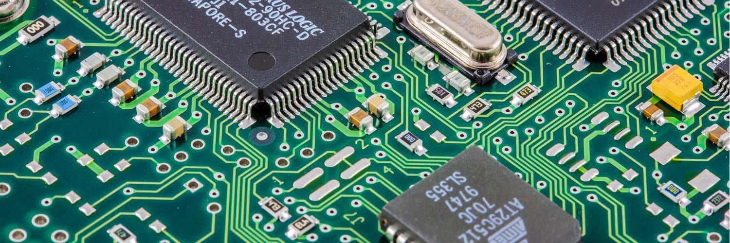
Surface mount resistors are the go-to form of resistor these days as they can be used in today’s high volume automated manufacture.
But for many engineers and hobbyists, moving from through-hole to SMT feels like a big leap. When using these resistors, understanding the nuances of SMD (Surface Mount Device) resistors is critical.
Here is a breakdown of what you need to know, based on our latest deep dive at Electronics Notes:
1. Why SMT? It’s not just about size.
While miniaturization is the obvious benefit, SMT resistors offer technical advantages that through-hole components can't match:
✅ Lower Parasitics: Their small size and lack of leads mean significantly lower stray inductance and capacitance—essential for high-frequency RF applications.
✅ Automated Assembly: They are designed for high-speed pick-and-place machines, drastically reducing manufacturing costs and increasing reliability.
✅ High Density: You can pack far more functionality into the same PCB real estate.
2. Decoding the Package Sizes
SMD resistors are typically referred to by a four-digit code (e.g., 0805, 0603, 0402). These numbers represent the dimensions in hundredths of an inch.
• 1206: Great for prototyping; less difficult to hand-solder.
• 0603 & 0402: The industry workhorses for consumer electronics.
• 0201 & 01005: Used in ultra-compact tech like wearables (nearly impossible to rework by hand!). Being used increasingly.
Note: there is also a package sizing code based on the metric system, but the imperial system is by far the more widely used.
3. Power and Tolerance Matters
Because they are so small, power dissipation is a key constraint.
• A standard 1206 resistor might handle 0.25W, while an 0402 might only handle 0.0625W.
• Design Tip: Always de-rate your resistors. Running them at 50-60% of their maximum rated power improves long-term stability and reliability.
• Most modern SMT resistors use metal film technology, offering excellent tolerances (1% or 2% are now standard and affordable).
4. Reading the Codes
Unlike the colorful bands on axial resistors, SMD resistors use a numerical system:
• 3-digit code: This is the most common type of code. First two are significant figures, the third is the multiplier (e.g., 103 = 10,000Ω or 10kΩ).
• 4-digit code: Used for high-precision resistors (e.g., 1002 = 100 x 100 = 10kΩ).
• Note: Many ultra-small packages (0402 and smaller) have no markings at all—organization in your lab is key!
Want the full technical breakdown, including power rating tables and marking charts?
For more information, check out the link in the comments below.
#ElectronicsEngineering #resistors #HardwareDesign #SMT #ElectronicsNotes #EngineeringTips #electroniccomponents
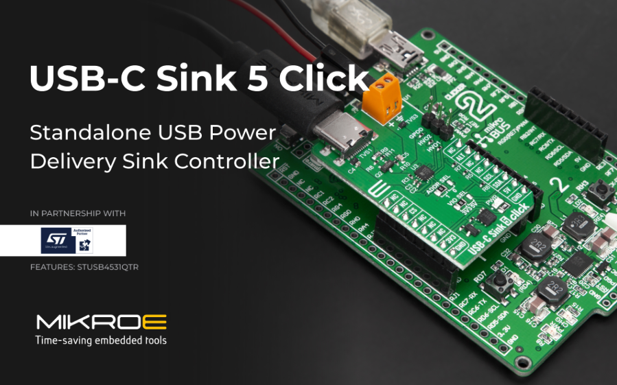
Say goodbye to legacy barrel jacks and upgrade to modern USB-C power!
MIKROE is thrilled to announce the launch of the USB-C Sink 5 Click from MIKROE—designed to bring seamless, standard-compliant USB Power Delivery to your next embedded design.
Powered by the STMicroelectronics STUSB4531QTR controller, this compact add-on board lets your embedded systems autonomously negotiate and manage power (from 5V up to 20V) directly from modern USB-C chargers.
Key Highlights:
* Versatile Applications: Perfect for wearables, mobile gadgets, high-end portable instruments, and retrofitting legacy DC inputs in field-deployed devices.
* Smart & Autonomous: Features autonomous USB PD contract negotiation via Autorun mode, internal non-volatile memory for default PDO configuration, and dead battery mode support.
* Robust Protection: Built-in VBUS monitoring, input power path control, integrated protection/discharge functions, and high-voltage surge protection.
* Plug-and-Play Simplicity: mikroBUS™-enabled with built-in ClickID for automatic host system identification, backed by open-source mikroSDK libraries and ready-to-use projects on EmbeddedWiki.
"USB-C Sink 5 Click is perfect for wearables and mobile gadgets that need to draw power from modern USB-C chargers instead of traditional barrel jacks." — Nebojsa Matic, CEO of MIKROE.
Ready to cut your development time and modernize your hardware? Check out the link in the comments to learn more about the USB-C Sink 5 Click and explore over 2,000 other mikroBUS™ add-on boards!
#MIKROE #EmbeddedSystems #USBC #PowerDelivery #HardwareDesign #IoT #Wearables #Engineering
@mikroel
What's your most useful / favourite electronics book.
Without a doubt mine is: The Art of Electronics. It is packed full of the information I need. Practical & yet descriptive with the right amount of mathematics.
Check it out on Amazon .com (sponsored): https://t.co/yuU1RWuVG8
Are your 10 nF capacitors actually delivering 10 nF in you circuit design?
If you’re working with high-capacitance MLCCs (Multi-Layer Ceramic Capacitors), you might be falling into ‘The Voltage Trap.’
One of the most counterintuitive traits of Class II ceramic capacitors (like X7R, X5R, and Y5V) is that their effective capacitance drops when a DC voltage is applied.
Shockingly , when operating near their rated voltage, some MLCCs can lose as much as 50% of their nominal capacitance.
Why does this happen?
Class II dielectrics rely on Barium Titanate (BaTiO_3), a ferroelectric material.
When a DC voltage is applied across the plates, the internal electric field "pins" the crystal domains in place. Because these domains are locked down, they can no longer freely polarize in response to AC signals—causing the effective capacitance to collapse.
How to combat DC bias shift in your designs:
1️⃣ Derate aggressively
Don’t run a 6.3V MLCC on a 5V power rail. Step up to a 16V or 25V part. Operating an MLCC at 20% to 30% of its rated voltage retains the vast majority of its nominal capacitance.
2️⃣ Switch to Class I dielectrics for precision
For timing circuits, filters, or sensitive analog paths, use Class I ceramics like C0G (NP0). They use non-ferroelectric materials and exhibit virtually zero capacitance shift across voltage, temperature, or time (though you'll trade off volumetric density).
3️⃣ Verify with simulation tools before freezing your BOM
Never trust the headline capacitance value on the reel. Use tools like Murata’s SimSurfer or KEMET’s K-SIM to view true capacitance curves under your exact DC operating voltage and ambient temperature.
Engineers: What’s your default voltage derating rule of thumb for MLCCs on power rails?
For more information, check the link below.
#HardwareEngineering #capacitors #ElectronicsEngineering #PCBDesign #electronicsnotes #circuitdesign
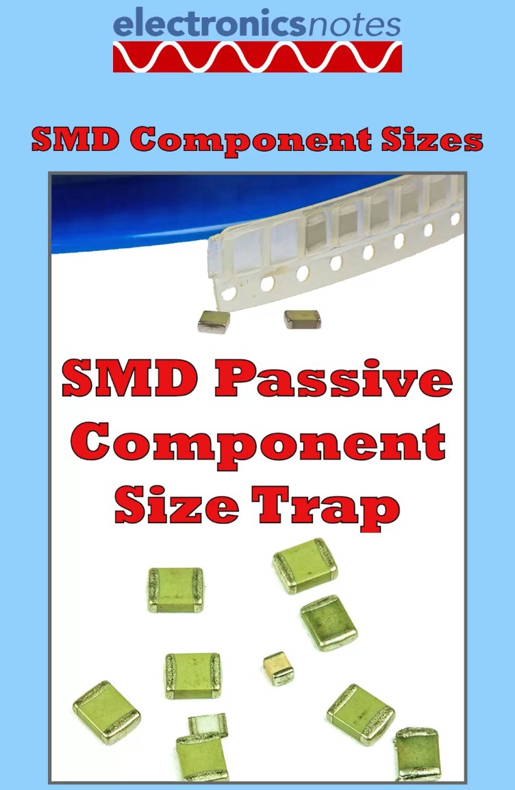
Have you ever encounter the SMD passive component size trap.
It could wreck your next project, so watch my latest TIikTok video so you don't fall into it.
Watch now: https://t.co/PbsIzZDCJj
What's your most useful / favourite electronics book.
Without a doubt mine is: The Art of Electronics. It is packed full of the information I need. Practical & yet descriptive with the right amount of mathematics.
Check it out on Amazon .com (sponsored): https://t.co/yuU1RWuVG8
@SJFriedl I’ve found it really good. There are few books I recommend as much as I do this one. Not an easy read to go all the way through - I use it as a reference book.
20 OCTOBER 2026
Fact of the day:
It was on 20th October 1984 that Paul Dirac died - he was a British theoretical physicist and considered as a founder of the field of quantum physics.
Electrolytic capacitors can have a bad name . . . but not if you use them correctly.
Here is my quick resume of what they are, where they are used and my rules for ensuring they work well.
Check out my YouTube video now: https://t.co/40GIqiSExa
#capacitor#capacitors #electrolyticcapacitors #learningelectronics #electronicsnotes
Want to know what Slew Rate is?
Check out my latest TikTok video where you can see exactly what it is and the effect it can have on the waveforms in your circuit.
Check it out now: https://t.co/HW934EM5vK
#opamp#slewrate#learningelectronics#electronicsnotes
Quadrature Amplitude Modulation (QAM) Explained
QAM is a signal modulation technique that combines amplitude modulation (AM) and phase modulation (PM) to transmit data more efficiently. Here's how it works:
- Amplitude Modulation: Varies the strength of the carrier wave.
- Phase Modulation: Changes the phase of the carrier wave.
In QAM, both amplitude and phase are varied simultaneously but independently, allowing for the transmission of two separate signals on the same frequency. This method significantly increases the bandwidth utilization compared to using either AM or PM alone.
How Does QAM Work?
- Quadrature Signals: Two carrier waves are used, which are 90 degrees out of phase with each other (hence "quadrature"). One signal modulates one carrier, and the other modulates the second carrier. When the two signals are combined the overall effect is that of both amplitude and phase being modulated - see diagram.
- Constellation Diagram: QAM signals can be represented in a constellation diagram where each point represents a unique combination of amplitude and phase. For example:
- 16-QAM uses 16 points to represent data, allowing 4 bits per symbol.
- 64-QAM uses 64 points, representing 6 bits per symbol.
- Symbol Rate vs. Bit Rate: With QAM, you can pack more bits into each symbol, thus increasing the data rate without needing more bandwidth.
Applications of QAM:
- Digital TV and Cable Systems: QAM is widely used in digital cable TV systems to deliver multiple channels in the same frequency band.
- Wireless Communications: Including mobile / cellular phones, Wi-Fi, etc where higher-order QAM like 256-QAM is used to boost speeds.
- Modems: ADSL and cable modems utilize QAM for high-speed internet connections.
Advantages:
- Bandwidth Efficiency: Carries more data per hertz of bandwidth.
- Robustness: Can adapt to different channel conditions by adjusting the modulation scheme.
Challenges:
- Complexity: Higher QAM orders require sophisticated receivers to demodulate signals accurately.
- Susceptibility to Noise: Higher order QAM is more sensitive to noise, which can degrade signal quality.
QAM stands as a cornerstone in the evolution of communication technology, enabling the high data rates we enjoy today. Whether you're streaming HD content or browsing the web at lightning speeds, there's a good chance QAM is quietly working behind the scenes to make it all possible.
For more information, check out the link in the comments.
#quadratureamplitudemodulation #qam #modulation #radiosignals #RFmodulation #RFdesign #electronicsnotes
Stuck by an obsolete or out-of-stock transistor?
Whether you’re repairing a classic piece of gear, prototyping a new circuit design, or dealing with supply chain gaps, you will eventually face a common hurdle: The exact transistor you need is completely unavailable. I’ve been there a number of times.
The good news? Because transistor specifications have a high degree of overlap, you don’t need the exact part number to get the job done.
You just need to know how to pick a proper substitute.
Here’s my 6-step checklist to safely narrow down a cross-reference or replacement transistor without blowing up your circuit:
1️⃣ Verify the Polarity & Material First
It’s the absolute bare minimum: NPN must replace NPN, and PNP must replace PNP. Equally important is the material. Silicon (approx. 0.6V base-emitter drop) and Germanium (approx. 0.2V–0.3V drop) cannot be casually swapped because the circuit’s biasing relies heavily on this voltage.
2️⃣ Check Voltage Breakdown (VCEO/ VCBO)
Ensure the replacement transistor can withstand the circuit's maximum voltages. The replacement ratings should always be equal to or greater than the original. (Pro-tip: If you don't have the original datasheet, aim for a maximum operating voltage that is at least twice the circuit’s rail voltage).
3️⃣ Match Current Handling (IC(max)
The substitute transistor must be capable of passing the required maximum continuous current. Your replacement's maximum collector current (I_C) should be \ge the original.
4️⃣ Look closely at Current Gain (hFE / beta)
While gain inherently varies significantly even within the same batch, you want a similar range. In most general-purpose circuits, choosing a replacement with a slightly higher gain is perfectly safe, but a lower gain might starve the circuit.
5️⃣ Watch the Frequency Limit (fT)
Make sure the transition frequency (fT) is adequate for the circuit's operation (especially in RF or high-speed switching). However, beware going too high! Choosing a substitute with a massively higher fT than required can inadvertently introduce unwanted circuit oscillations.
6️⃣ Don't Ignore Package & Pin-outs
Physical sizing matters—especially if you're dealing with heatsinks or compact PCBs. More importantly, double-check the pinout configuration. Just because two small-signal transistors look identical (like TO-92 packages) doesn't mean their pins are both E-B-C. A mismatched pinout is a quick way to let the magic smoke out.
What if you can't find the original datasheet at all?
You can still reverse-engineer a safe bet! Check the operating voltage of the power rail, deduce the material by measuring the base-emitter voltage drop of a working neighbor transistor (if available), and gauge power dissipation limits by matching the physical case style.
For more information, check out the link in the comments. 👇
#ElectronicsEngineering #CircuitDesign #PCBRepair #ElectricalEngineering #Hardware #EmbeddedSystems #electronicsnotes