NTT Docomo joined Starlink Direct to Cell in Japan, and millions of Japanese users immediately flocked to the carrier’s satellite service
More than 5 million users connected in just over two months after launch
No special satellite phone or additional hardware. Just normal smartphones connecting directly to Starlink satellites when cellular coverage disappears
This shows how powerful Starlink Direct to Cell is for both mobile users and carriers
Starlink is literally driving millions of users toward carrier services by giving them coverage traditional cell towers cannot provide
Starlink is making mobile networks more valuable than ever
Two reasons why we integrated Grok 4.5 inside Perplexity Computer within a few hours:
1) It scored the best on our evals and was the most cost effective option
2) ZDR was available from the get go and that’s what our customers want
5 years ago someone tried to ratio an Elon prediction that was already 10 years old at the time. Guess they didn’t know that where everyone sees points, Elon sees vectors.
Pretty nuts prediction considering the circumstances.
The fact this one dude - by himself - can walk into any state and find blatant fraud everywhere he goes proves two things: 1) the fraud is rampant at an unprecedented scale and 2) the government agencies who are supposed to protect our tax dollars are either completely incompetent or complicit in the fraud.
@beffjezos I say both energy and mass, as they are separate scarcities for practical purposes, despite being technically “equivalent”, as described by Einstein’s famous equation.
Our solar system has only a tiny percentage of non-solar atoms with which to build things.
GOOD NEWS 🇮🇳 With AI5 already heading to production, Tesla is actively staffing up its custom silicon team in India to tape out AI6 and Dojo 3 🔥
For anyone outside the semiconductor industry, bringing a custom AI chip to life requires a highly specialized pipeline.
It all starts with the ASIC RTL Design Engineer, the person who actually writes the code. They architect the logic, network subsystems, and memory pipelines that form the digital "brain" of the AI accelerator.
Next comes Formal Verification, which uses rigorous mathematical logic to prove that those individual design blocks are 100% bug-free. This phase hunts down the absolute worst-case edge scenarios that traditional simulation testing entirely misses.
Then, the SOC Verification Engineer steps in to look at the big picture. They assemble all those verified blocks into a complete system, building massive simulation environments to ensure the entire chip talks to the firmware, manages power correctly, and boots up flawlessly.
In parallel, Design for Testability (DFT) Engineers build an internal health-check system straight into the hardware. They embed specialized testing structures and generate mathematical test patterns so automated factory machines can instantly screen out physically flawed chips at mass scale.
Once the system logic and test structures survive these gauntlets, the design officially achieves "RTL sign-off".
From there, the Physical Design Engineer takes the handoff for the final sprint. This team takes that proven digital blueprint and physically maps out exactly where those billions of microscopic transistors will live—routing the tiny wires and dialing in the electrical timing to absolute perfection.
Completing these physical layout steps is the true, definitive final gate a design must pass to officially tape out AI6 and Dojo 3 🔥
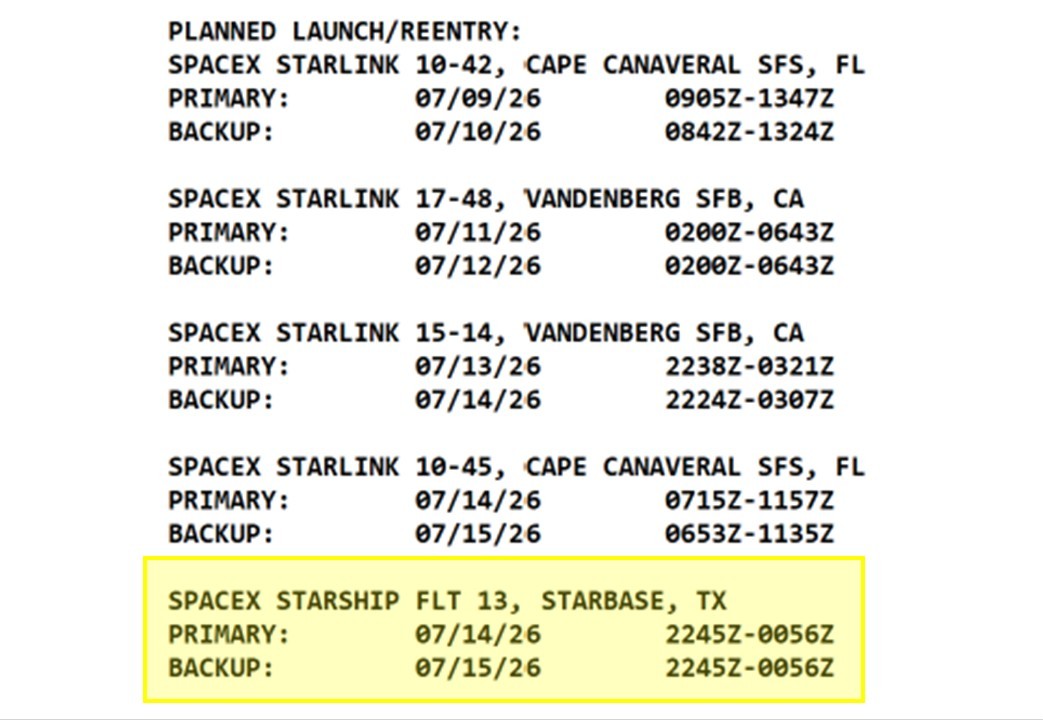
Missed this first time around. 20 real Starlink V3 sats. Will deploy solar arrays and antennas and attempt ground station connection. Very big test toward functional Starlink V3 deployments by ~EoY.
First functional launch is significant inflection in Starlink V3 ramp which is equivalent to global bandwidth capacity ramp.
Very good to see real sats on board. Hopefully we get to see them deployed from pez as well!
GOOD NEWS 🚨 Tesla has re-engineered the battery edge with metal origami to attack the charging bottleneck ⚡️
Imagine trying to empty a stadium through a handful of narrow gates. That is how a conventional tabbed cylindrical battery collects current.
For decades, most cylindrical cells have relied on one or a few metal tabs to carry current out of long strips of tightly wound electrode. Current collected far from those tabs must travel laterally through thin metal foil, concentrating resistance and heat around a small number of exits.
Tesla’s original 4680 architecture attacked that bottleneck with distributed edge contact. But forming that quasi-tabless edge can still require cutting the foil into a dense forest of individual fingers or flags, adding laser equipment, debris control, and many potential weak points.
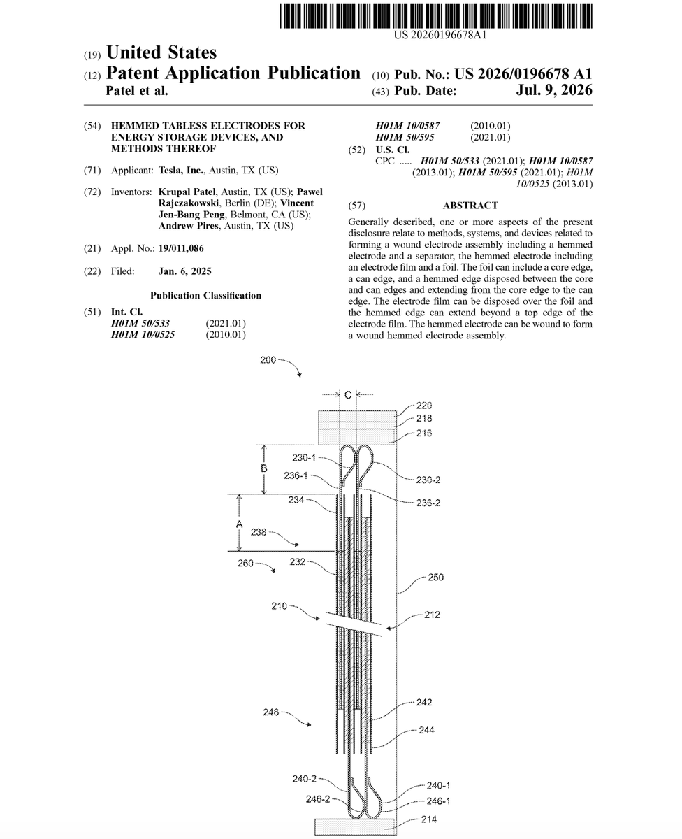
Tesla’s newly published patent application US 2026/0196678 A1, released on July 9, 2026, reveals a different approach: do not cut the foil into fingers at all. Fold its uncoated edge into one continuous microscopic hem.
As the electrode is wound, each turn of that hem contacts the next. Factory tooling can then flatten the loops into a dense, uniform end-face interface and connect it to a current collector. It is metal origami applied to one of the hardest problems in battery manufacturing.
The result could preserve the electrical advantage of full-edge current collection while deleting entire families of tabbing, notching, debris-handling, and exhaust equipment. It is a classic example of Tesla’s preferred engineering philosophy: the best process step is the one the factory no longer needs.
To appreciate why this folding technique matters, it helps to look at the severe complications it is designed to replace.
⚖️ The problem: The structural vulnerabilities and bottleneck effects of traditional discrete tabs
In a standard battery jellyroll, which is the industry term for the tightly wound cylinder of electrochemical components inside a cell, forming or attaching physical tabs to the electrode sheets is a constant headache for production engineers. These distinct metal tabs add local thickness to the wound assembly, complicating the winding process and risking punctures in the thin separator layers that keep the positive and negative sides from touching. When these protective barriers fail, an internal short can produce rapid heating and, in severe cases, trigger thermal runaway.
Beyond the physical space they occupy, tabs create a massive geometric bottleneck for electrical current. Current collected from distant portions of the electrode must travel laterally through the thin foil before reaching the tab. This long transit path significantly raises internal resistance, which is the electrical friction that fights against the flow of current.
This friction generates immense, unwanted heat during fast charging. Manufacturing these current-collection structures can also require precision cutting or notching, alongside debris-extraction machinery designed to keep microscopic metal fragments away from the active chemistry.
Faced with these compounding physical and mechanical bottlenecks, engineering teams had to rethink the entire architecture of the electrode edge.
💡 Tesla's solution: Continuous edge folding to establish an integrated tabless current path
Tesla completely flips this design by rolling or hemming the top and bottom margins of the conductive metal foil sheets before they are wound together. Hemming is the process of folding over a raw metal edge just like the hem on a piece of clothing. Instead of relying on a few sparse tabs, the entire exposed edge of the foil is folded into a continuous loop structure that extends just beyond the active-material coating.
The positive and negative electrode foils can each receive a continuous hem, positioned at opposite ends of the jellyroll. As the electrodes are wound, each turn of the hem contacts the turn beside it.
Tesla can then flatten or iron the projecting loops to produce a compact, nearly void-free end face. A collector plate is joined across that surface, gathering current from many points around the entire spiral instead of a few isolated tabs. Joining is not limited to laser or ultrasonic welding. The application also lists forced contact, soldering, brazing, and adhesive joining. In some versions, the can or lid itself can double as the current collector, potentially eliminating a separate component.
Once the fundamental physics of the folded edge are established, the next challenge is choosing a battery coating method tough enough to handle the mechanical stress.
🧪 Dry-electrode compatibility: Pairing two manufacturing simplifications
The hem does not depend on a particular electrode-coating process, but it fits naturally beside Tesla’s dry-electrode program. In a conventional wet process, active powders and binders are mixed with solvent, coated onto foil, and passed through large drying and solvent-recovery systems. In the dry version described by Tesla, dry particles are mixed with a fibrillizable binder that forms a microscopic reinforcing web. The resulting film can support itself before being pressed onto the metal foil.
PTFE is one possible fibrillizable binder, although the application lists several alternatives. Binder content may fall between 1 and 10 weight percent, while disclosed active-material content extends as high as 99.9 percent.
These technologies simplify different parts of the line. Dry processing attacks mixing, coating, drying, and solvent recovery. The hem attacks tab cutting, notching, debris extraction, and current collection. Their importance lies in how naturally the two factory simplifications can work together.
Making this dual factory simplification work in the real world requires managing dimensions down to the micron level.
📐 Geometric tolerances: Microscopic calibration of length, height, and width variables
Tesla defines three variables around the fold: separation A, loop height B, and loop width C, which establish broad design windows for the physical shape of the fold.
Length A is the uncoated foil distance between the active film and the beginning of the hem. The application describes values from 0 to 2 millimeters and specifically lists 1.14 millimeters as one example. This separation can be important because it can reduce the active material’s thermal exposure during collector joining.
Height B represents the total vertical profile of the projecting hem and may range from 0.1 to 3.0 millimeters, defining how far the structure projects into the limited overhead space inside the cell. Width C defines the loop width before compaction, measuring between 0.05 and 0.9 millimeters. These are broad design windows rather than proven optimum limits. Tesla also allows the height, width, and shape to change along the length of the electrode, giving engineers room to tune the interface for winding, flattening, and joining.
Controlling these microscopic boundaries allows engineers to experiment with the precise physical profile of the fold itself.
🌀 Fold geometry: Turning a fragile foil edge into a controlled contact surface
The simplest embodiment forms the foil into a rounded teardrop loop. Adjacent loops touch as the electrode winds around the core, creating repeated metal-to-metal contact around the spiral.
The teardrop is not the only option. Tesla also describes rectangular, triangular, trapezoidal, rounded, and fully collapsed profiles. The engineering objective is therefore broader than creating one exact shape. The goal is to form a continuous edge that survives winding, contacts neighboring turns, and can be flattened into a reliable collector interface.
While a single teardrop shape handles basic contact, more complex variations give factory tools alternative mechanical properties to play with.
🔄 Multi-loop configurations: Changing fold direction, contact area, and collapse behavior
Tesla also describes double-loop hems. Both curls can bend in the same direction or return in opposite directions, and neighboring windings may contact through either or both loops. These variations give engineers different amounts of metal, contact area, and collapse behavior to work with during flattening, offering different ways to balance mechanical robustness, contact area, and the geometry of the flattened interface.
No matter how many loops are folded into the foil, the true magic happens after the winding machinery finishes rolling the cell.
🏭 Post-winding finishing: Ironing both ends into production-ready interfaces
After the jellyroll is wound, Tesla can flatten both hemmed ends simultaneously rather than finishing each electrical pole in a separate operation. The application describes pressed plates, sliding or rolling pins, cone- or dome-shaped tools, and a harmonic flattening interface. These tools can apply planar, line, point, or dynamically moving pressure to collapse the loops into flat joining surfaces.
Factory equipment can also reshape the central opening after winding, restoring the circularity and cylindricity of the innermost layers. Once the collectors are joined, CT scanning or other non-destructive inspection methods can verify the hidden connections without cutting the finished cell apart.
With both ends perfectly flattened and packed with active conductive material, managing the internal electrical boundaries becomes highly critical.
🛑 Short-circuit protection: Strategic wrapping of insulative tape to isolate exposed conductive edges
The projecting hems sit close to the conductive cell housing, making electrical isolation essential. Tesla places insulating tape around the end of the jellyroll near the hem. Depending on the configuration, the tape can sit beneath or over the current collector, helping prevent the exposed electrode edge from contacting the can.
Even with robust short-circuit insulation in place, these internal connections must still survive the intense mechanical stress of everyday driving.
🛡️ Strain relief: Patterning current collectors to protect rigid connections
The current collector discs joined to the hemmed folds can be exposed to significant internal mechanical forces. As battery cells undergo rapid charging and discharging, the internal materials physically swell and contract. This continuous breathing can place axial and torsional stress on the collector interface, gradually fatiguing a completely rigid joint.
The collector may be a solid metal disc. In other embodiments, Tesla removes triangular, circular, square, rectangular, or other geometric regions from the plate. These openings introduce flexibility and help decouple axial or torsional stress from the welded interface. Instead of forcing every internal movement directly into a rigid joint, the patterned plate can flex while preserving the electrical connection. Tesla goes one step further in some configurations by allowing the lid or can itself to serve as the collector.
Giving the cell layout this kind of structural flexibility means the underlying architecture can easily support a massive variety of battery ingredients.
🔋 Chemical-agnostic architecture
The hem is a current-collection and manufacturing architecture rather than a new chemistry. Tesla describes it across lithium iron phosphate, lithium manganese iron phosphate, lithium nickel manganese cobalt oxide, and lithium nickel cobalt aluminum oxide cathodes. It also covers graphite, graphene, and silicon-based anodes, multiple conductive additives, and both wet- and dry-processed electrode films.
That breadth matters because the folded edge is not tied to one specific 4680 formulation. It could follow the cell through future changes in cathode chemistry, silicon content, electrolyte composition, and active-material loading.
Because this structural framework is highly adaptable to different cell chemistries, its true value is realized in how it reshapes the factory floor.
🛠️ Leaner production lines: Driving down factory footprint by abandoning high-speed cutting modules
One of the biggest wins from this technology is the radical simplification of the battery assembly line. A hemmed-electrode line may no longer need separate tabbing, slitting, notching, flag-interleaving, or foil-debris handling equipment.
Removing those operations can reduce equipment complexity, floor space, energy consumption, scrap, and labor while improving web speed, tension control, and geometric precision. The absence of slits provides another advantage. The continuous foil edge is less vulnerable to bending and tearing under tensile loads during high-speed web handling. Tesla also identifies improved electrolyte fill time as a potential benefit, because the simplified end structure can leave more accessible internal overhead volume.
Slashing machinery complexity and factory floor space is a massive win for manufacturing, but the ultimate test is how these changes alter the actual performance of the cell.
📉 Performance and safety advantages: Lowering internal resistance and accelerating gas egress
By making the entire edge of the foil an active electrical terminal, which serves as the massive contact zone where electricity enters or exits the cell, Tesla shortens the distance current must travel down to a fraction of a millimeter. This design removes the electrical bottlenecks responsible for sluggish power delivery and localized overheating.
Lower internal resistance, meaning the inherent electrical friction that slows down moving electrons, ensures the cell stays cool even under intense loads. This thermal stability, the ability of the system to maintain a safe operating temperature without overheating, unlocks much faster supercharging rates and allows the vehicle to draw massive bursts of power for high-performance driving without triggering thermal throttling, a built-in safety measure that forces the battery to automatically restrict power output to prevent heat damage.
Beyond day-to-day electrical efficiency, this compact architecture significantly alters the interior layout to improve cell safety during extreme failure events. Tesla identifies runaway-gas egress and free internal overhead volume as key advantages of the folded edge. Conventional tabs, flags, and bulky joining structures physically crowd the ends of the jellyroll, trapping gases if a cell begins to fail and build up pressure.
In contrast, the uniform and streamlined hemmed interface leaves gases a much clearer, unobstructed route toward the cell’s designed safety vent. While this layout change does not prevent thermal runaway by itself, allowing faster pressure relief can dramatically reduce the dangerous buildup of gas inside a failing cell.
Balancing all of these immediate electrical, thermal, and manufacturing upgrades reveals the grand scale of where this technology is heading next.
🚀 How this patent application could contribute to Tesla’s present and future
This hemmed architecture could become another piece of Tesla’s effort to simplify the 4680 production line. The original tabless design shortened the electrical path by replacing a few isolated tabs with distributed edge contact. This application pushes the idea further by replacing a laser-cut forest of individual foil fingers with one continuous, slit-free folded edge.
That change attacks several expensive manufacturing steps at once. The application says a hemmed-electrode line may no longer require dedicated tabbing, notching, flag-interleaving, debris-handling, and associated exhaust equipment. It also eliminates the slits that weaken the foil under production-line tension.
The hem fits naturally beside Tesla’s dry-electrode program, even though either technology can operate without the other. Tesla’s 2020 Battery Day roadmap projected a 10-fold reduction in energy use and footprint for the dry-electrode coating step and attributed an 18% reduction in battery cost per kilowatt-hour to its overall cell-factory innovations. Tesla later estimated that dry-electrode manufacturing could reduce energy consumption across the cell-manufacturing phase by more than 70%. The hemmed edge adds another layer of simplification by shrinking the cutting, cleaning, and current-collection portions of that factory.
The material calculation is also reasonable when presented as a representative formulation. If an electrode contains 1 to 2% binder and roughly 1% conductive additive, the active material can account for approximately 97 to 98% of the film by weight. The folded edge does not create that formulation, but a slit-free current collector can support the same broader push toward simpler, heavily loaded electrodes.
Electrically, the continuous edge gives current many short routes out of the jellyroll instead of forcing it through a few narrow tabs. Lower resistance means less heat for the same power, a valuable advantage as Tesla pushes pack charging beyond 250 kW. That territory is already real. Model Y supports up to 250 kW, while Cybertruck can accept up to 325 kW at compatible V4 Superchargers. The hem’s potential contribution is not merely reaching those peak numbers, but sustaining high power with more uniform current flow and less internal heating.
Looking further ahead, moving from estimated cell-level values of 244 to 260 Wh/kg to 340 Wh/kg would represent an increase of approximately 31 to 39%. Reaching that level would require a combination of higher-energy cathodes, more silicon in the anode, greater active-material loading, less inactive material, and better thermal control. The hemmed architecture could support that trajectory by reducing resistance, simplifying current collection, and freeing internal overhead volume that does not store energy.
In other words, the hem is not the new chemistry. It is the manufacturing and electrical architecture that could help Tesla package more advanced chemistry into a large cylindrical cell without recreating the cutting complexity and thermal bottlenecks it was trying to escape.
It’s rare that we show the many accomplishments of our Tesla teams. We execute so much within a day, a week, a month, and a year. This video acts as an acknowledgement to our dedicated employees, along with a stethoscope to the pulse of all of our Tesla employee’s hearts.
The path to launch is filled with obstacles and success is only possible through the tireless efforts of many working together towards a common goal. “Critical Path” continues the ongoing Starship series, following SpaceX engineers through the final days before launch of the first Starship V3 and the challenges that come with development of the world’s most powerful and fully reusable rocket.
Same country investing an order of magnitude more into orbital data centers than the US. Wonder if there is something to that.🤔
Orbital infrastructure Cambrian explosion is coming whether the armchair engineers believe it’s possible or not.
SpaceX just released a new website for Starmind their upcoming AI satellite constellation
The new Starmind site now gives the first public look at the AI1 satellite, including:
• Thermal/vacuum cooling systems
• Solar power design
• Orbital AI compute architecture
Website: https://t.co/5prM8mdOxe
@Montebianco114 This was a slightly earlier version but the Starlink constellation was a bit off center.
We also built an HTML visualization on this analysis. https://t.co/35xV9MFO4w
Tesla is working toward achieving net-zero greenhouse gas emissions across its entire value chain by 2040
Tesla has already made insane progress toward net-zero emissions:
- The Supercharger network has been matched with 100% renewable electricity for five consecutive years
- Gigafactory Berlin-Brandenburg has matched 100% of its electricity usage with renewable electricity for three straight years