Three matrices no larger than a stamp encode the spin of every electron.
The Pauli matrices σₓ, σᵧ, σ_z are the unique 2×2 Hermitian matrices with eigenvalues ±1 that represent spin operators.
They satisfy σᵢσⱼ = δᵢⱼI + iεᵢⱼₖσₖ, linking matrix algebra to spatial rotations.
These same matrices form the elementary gates of every quantum computer and describe the nuclear spins imaged by MRI. Spin is written in 2×2 matrices.
Te imaginas no estudiar a último momento todo apurado y llegar sobrado de tiempo al parcial, ir re tranquilo xq terminaste de estudiar todo, te sentas y es como un trámite. Éxtasis.
No me estaría pasado
ALEPH HACKATHON — AUGUST 22 & 23!
Two days to build the best products and projects, accompanied by mentors, workshops and the incredible energy that characterizes the Aleph Hackathon. Registration is now open!
📍 IRL & Online | With multiple hubs across LATAM
Tengo está escena lamentable en mi escritorio xq mi cerebro decide todo el tiempo asignarle a la or el símbolo de la and. 500 ejercicios más tarde sigo confundiendolas, increíble
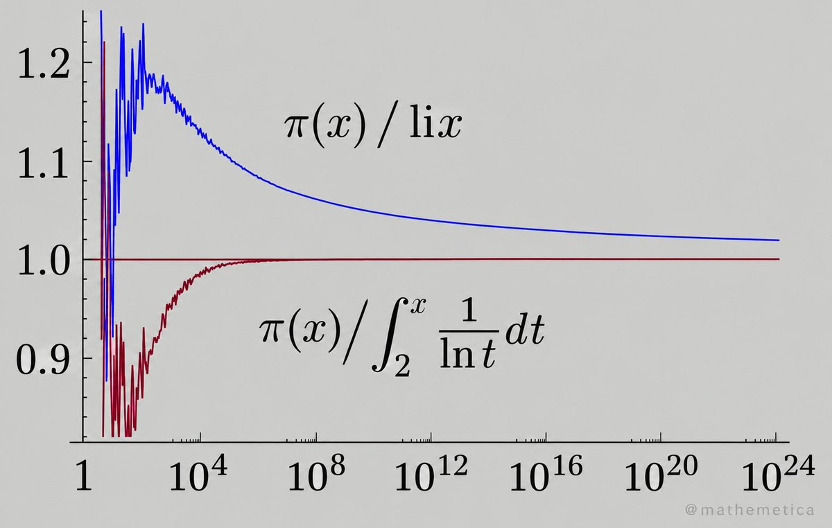
Primes look random, yet their count obeys a precise asymptotic law.
π(x) ~ x / ln x. The blue ratio slowly nears 1 from above; the purple ratio with li(x) = ∫₂ˣ dt / ln t locks onto 1 far earlier and stays tighter out to 10²⁴.
This is the Prime Number Theorem. It guarantees the dense supply of large primes that power RSA, elliptic-curve crypto, and every secure key you use online.
Asymptotics turn apparent chaos into digital trust.
@AngeluchoLink Cool, igual mi humilde mememotecnia de los últimos días (y viene funcionando un poco mejor) es q la anD es proDucto y su símbolo es la D jeje
I need an oscilloscope 👉👈
If anyone has a spare/old one lying around that they're not using anymore, please let me know. Doesn't have to be anything fancy. Plsss!!!
Transistor High Pass Filter Circuit Design
The transistor high pass filter circuit given below provides an easy to design two pole filter with unity gain. This means that the ultimate roll-off rate will be 12 dB / octave or 40dB / decade.
The active high pass transistor circuit design is quite straightforward, using just a total of four resistors, two capacitors and the single transistor.
The operating conditions for the transistor are set up in the normal way. R2 and R3 are used to set up the bias point for the base of the transistor.
Often this is set to give the base voltage at half the rail voltage so that the maximum voltage excursions can be made without running into the rail voltage.
The values of these resistors must also be set so that the overall value of the resistors in parallel does not affect the operation of the filter as we see below, whilst also being able to supply sufficient current for the base of the transistor.
The emitter resistor Re is the emitter resistor is calculated to give the required current through the transistor knowing the voltage on it as it will be 0.6 volts below the voltage that is on the base, for a silicon transistor. For a germanium transistor it is just 0.2 to 0.3 volts below the base voltage.
Knowing the voltage on the emitter, it is then just a simple a simple Ohm's Law calculation to determine the value of the emitter resistor.
The filter components are included in negative feedback from the output of the circuit to the input. The components that form the active filter network consist of C1, C2, R1 and the combination of R2 and R3 in parallel, assuming that he input resistance to the emitter follower circuit are very high and can be ignored.
The capacitors should be reasonably close tolerance types - ceramic, metal film, etc are ideal.
The equations for determining the component values provide a Butterworth response. This filter response provides maximum flatness within the passband at the expense of achieving the ultimate roll off as quickly as possible.
This has been chosen because this form of filter suits most applications and the mathematics works out easily. Although this may not be the form of filter needed for all electronic circuit designs, it is more than suitable for the majority.
The equations for calculating the values in the one transistor high pass filter are given below:
C1=2 C2
R3 = R1 R2 / (R1+R2)
So that the loading on the filter components is minimal and the calculations are not offset by the loading effect of the transistor itself:
Re (β+1) >> R1 R2 / (R1+R2)
fo = √ 2 / (4 π R3 C2)
Where:
Β = the forward current gain of the transistor
f0 = the cut-off frequency of the high pass filter
π = Greek letter pi equal to 3.14159
When designing the circuit, a little iteration may be required to optimise the value so that available components can be used and impedance values, etc can fall within acceptable limts.
Open-loop inverse kinematics drifts: tiny errors compound as you integrate
q(t) = ∫ J⁻¹(q) ẋ dt.
Add feedback:
q̇ ≜ J⁻¹(q)(ẋ_d + K e)
and the tracking error obeys ė = −Ke — exponential decay.
The same law keeps robotic arms, surgical robots and real-time character animation locked to their paths without drift.
Stability converts fragile open integration into trustworthy motion.