The MAC component takes my ethernet frame and adds its own transmission details. RGMII connects MAC with PHY chip. It's transmission logic takes MAC’s byte data and sends its 4 bits to PHY chip on both clock edges.
I've implemented components to build Ethernet frames. I now need to build MAC and RGMII components which take these frames and send it to PHY chip on FPGA. Since these are quite complicated, I won't be building them and pick them up from this repo: https://t.co/6hpVowiMwg
@cheaf25master Computer science isn't about making websites and writing APIs. Had that been the case then people without CS background wouldn't have become software developers.
Its not very visible, but this is the waveform I got after testing the full stack. The testbench stalls the receiver every 4th clock cycle, then checks all 298 bytes. It checks the 42 header bytes against an expected list and the payload against 0, 1, 2 ... 255.
It passes!
The whole stack is now one module! Inside is my byte counter which makes the payload, the UDP block wraps it, IPv4 wraps that, Ethernet wraps that al in their own headers.
Counter → UDP → IPv4 → Ethernet.
The first counter I posted a few days ago is now the data source.
Added the last layer to my Verilog packet stack: the Ethernet frame.
It puts 14 bytes in front of the IPv4 packet: destination MAC, source MAC, and the type code 0x0800, which means "IPv4 inside".
Same valid/ready handshake as the other blocks, so it just plugged in.
Watch this youtube video if you want to understand how to go from your RTL code to an actual chip design which can be fabricated.
https://t.co/U4U7jPVamf
@adityaag Writing software is easy and that opens our time to solving harder engineering problems. I am personally moving into hardware and building a deep contextual knowledge about a particular domain (Photonics, RF, etc.) where it was previously hard to contribute.
The data transfer happens on a rising clock edge where both valid and ready signals are high. Check all the waveforms below, and you would see the data changes occur when both the signals are high.
Working on these blocks taught me how me about the valid/ready handshake protocol. Basically one block will send data to the other block when valid and ready signals both are high.
The valid signal is set by the sender of the byte and the ready signal is set by the reciever of the byte. When valid is high, it means sender has a valid byte to send, and when ready is high, it means that reciever is ready to recieve.
Got the Ipv4 component working too! It sends its header first along with the checksum, and then passes along the udp data.
Also tested stalling behaviour and its working. The block doesn't forward the next byte until the previous one is accepted by the reciever.
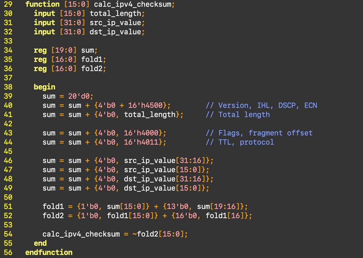
Learnt to write functions in Verilog. My IPv4 block needs a header checksum. You add up the header as 16-bit words, fold the carry back in, invert the result. I wrapped it in one function and call it in a single line. The checksum is ready before the first header byte goes out.
In classic verilog the function returns the value assigned to a variable with the same name as the function. Quite different from how it works in lanugages like C.