We are back!
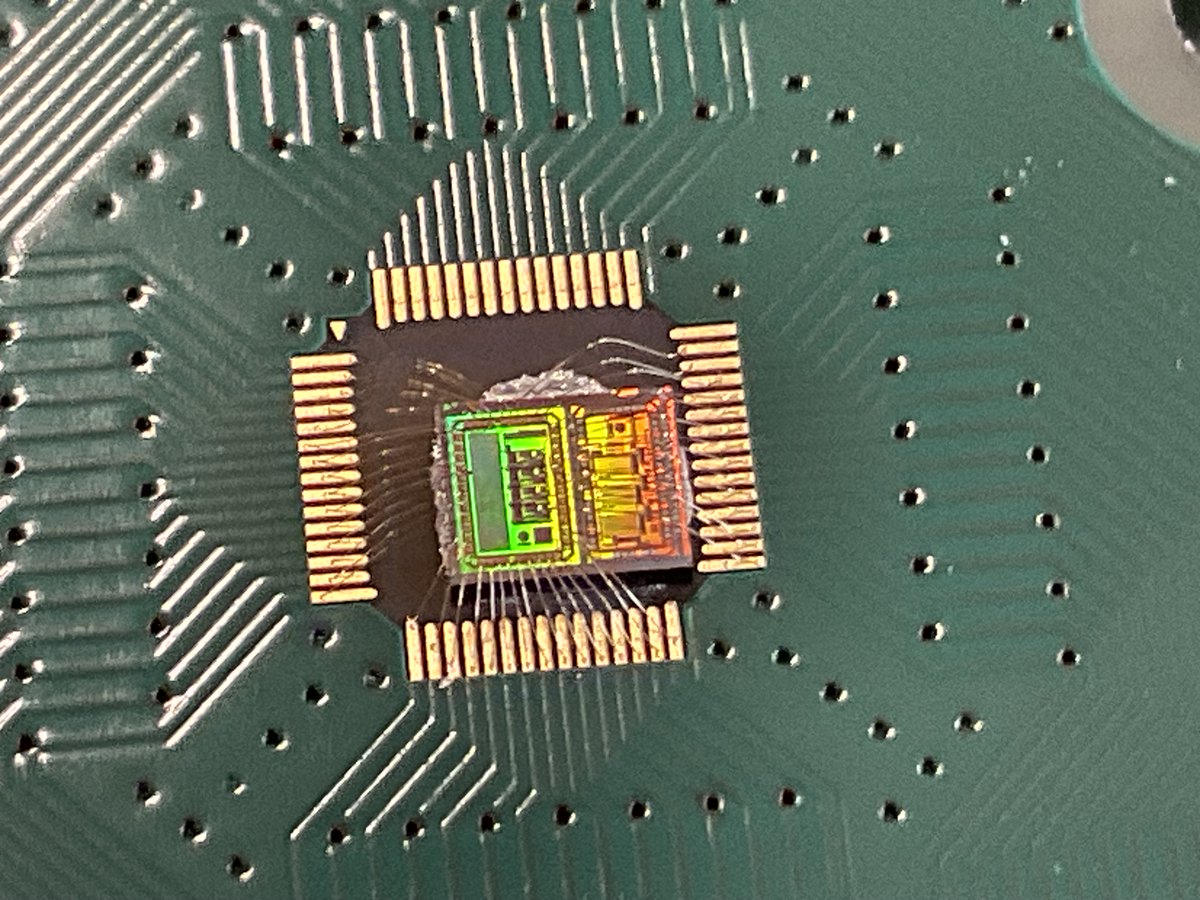
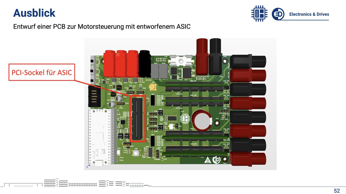
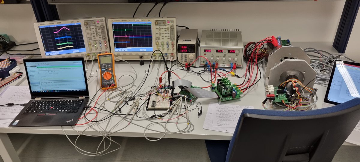
We finished the first semester with a successful mixed-signal ASIC design. During the meantime, we developed the power electronics necessary to power switched reluctance motors up to 320 Volts! Stay tuned.
@ElectronicsDrv#Powerelectronics#Microelectronics
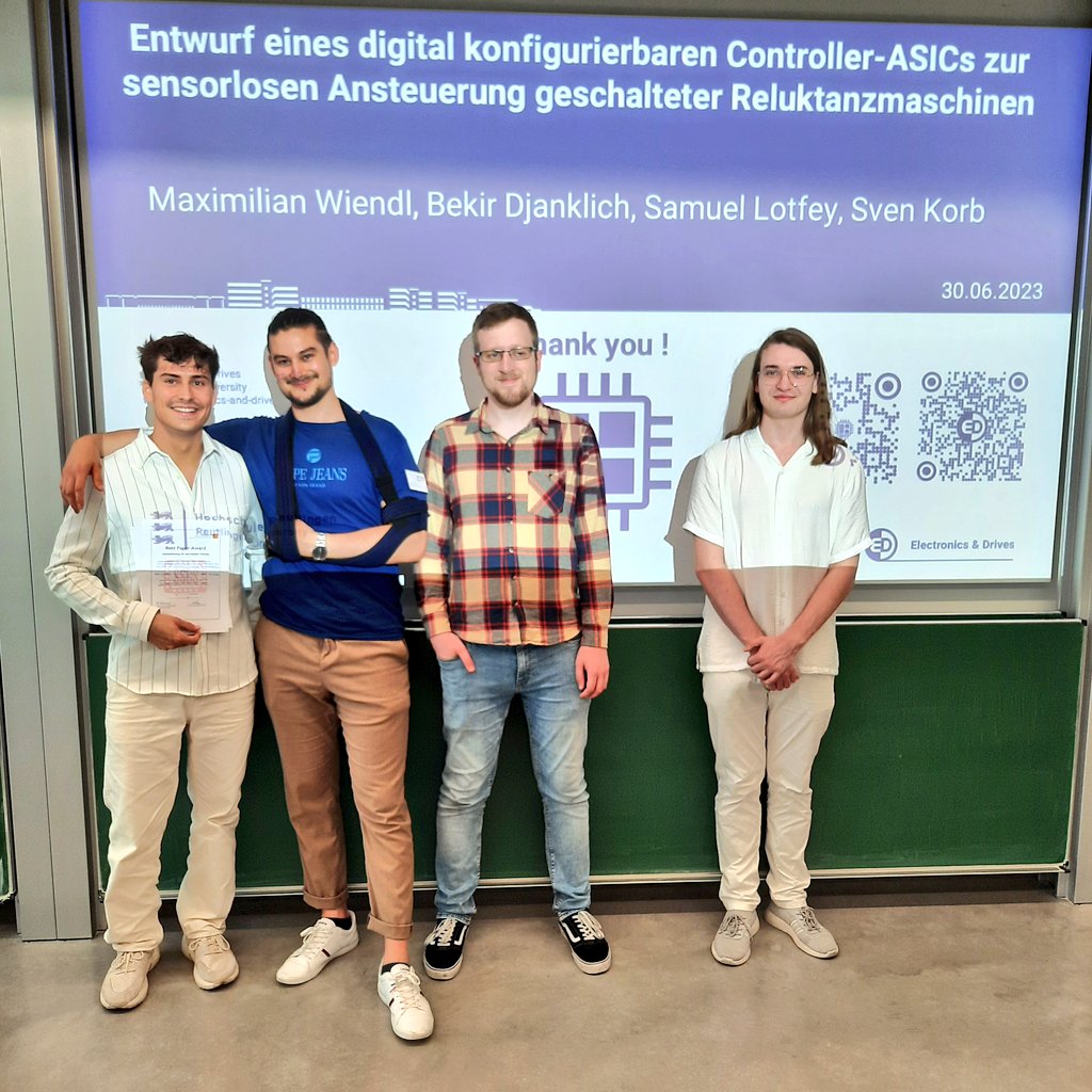
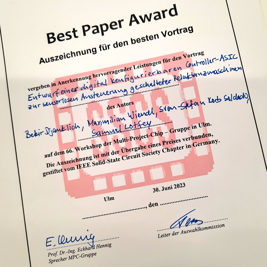
66. MPC-Workshop an der @THU_Ulm: Best Paper Award für unser #Master-Projektteam @EDRT_RIDE für seinen Beitrag zur Entwicklungen eines digital konfigurierbaren ASICs zur Ansteuerung geschalteter Reluktanzmotoren. Herzlichen Glückwunsch!
#Mikroelektronik @HS_Reutlingen
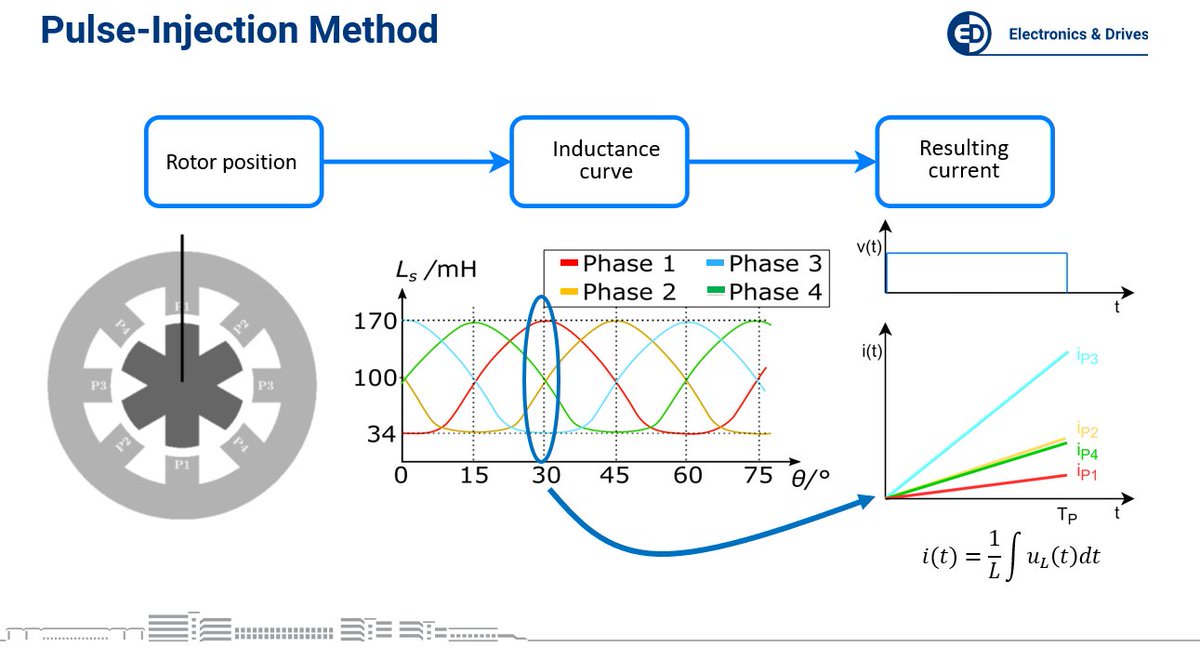
During StartUp we measure all phase currents of the SRM after a digitally adjustable time. These have a different di/dt due to different inductance values of the phases at the start position of the SRM.
@ElectronicsDrv#Powerelectronics#Microelectronics
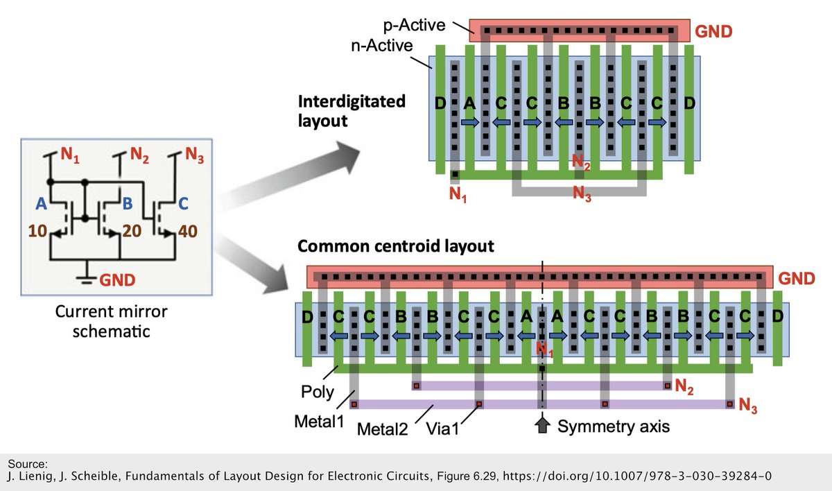
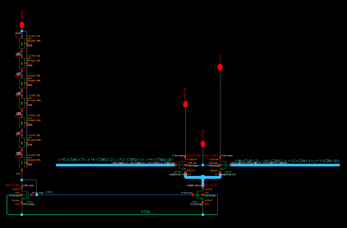
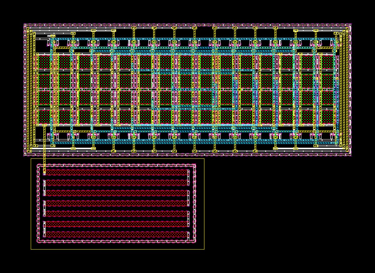
You can see the current mirror schematic and layout of the HCC .
The resistors and NMOS are built up from multiple identical basic elements in common-centroid arrangement. With this approach the influence of production tolerances is reduced.
#Microelectronics#Powerelectronics
Our SPI-based digital interface is tested on an FPGA.
Via multiple SPI packets, the string "Digitale Schnittstelle" is written into eight registers which are linked to a display as visual feedback.
@ElectronicsDrv#Microelectronics#Powerelectronics
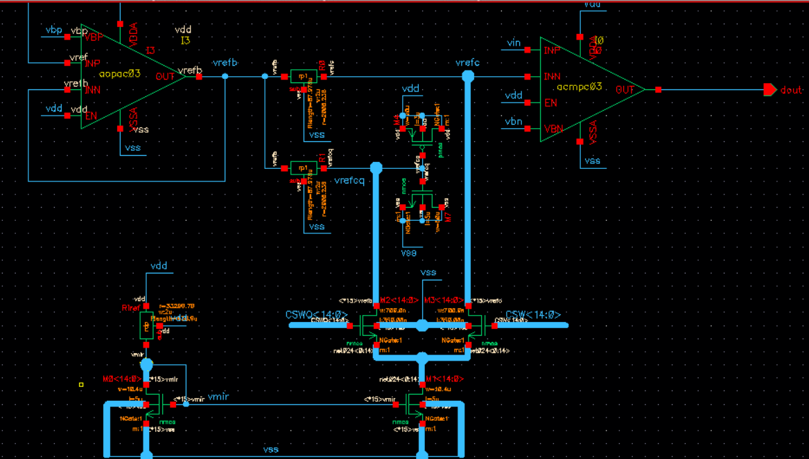
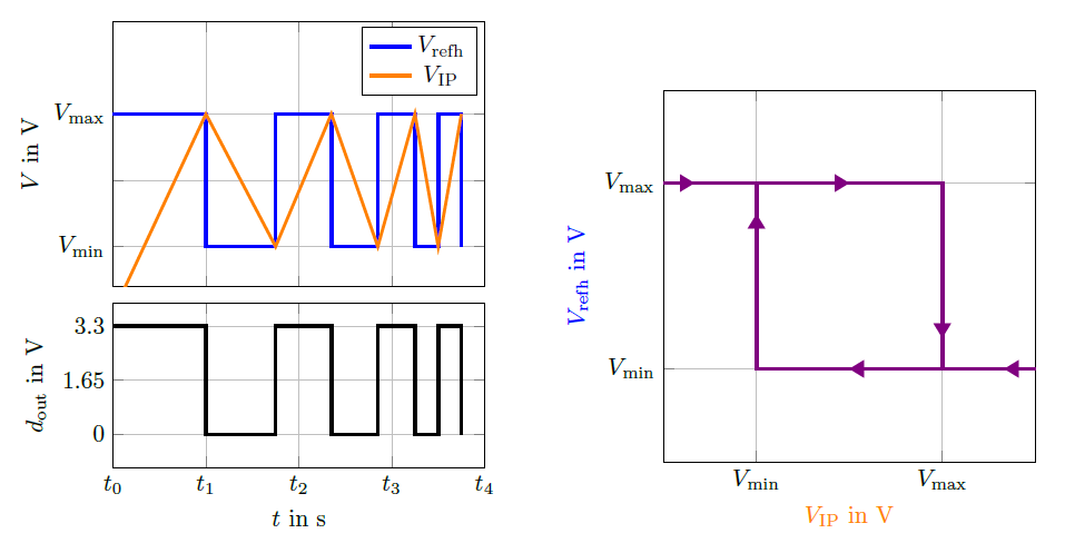
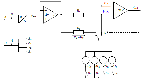
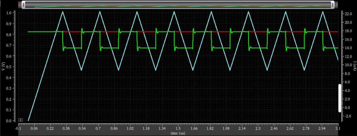
Part of the @EDRT_RIDE ASIC is the digitally adjustable hysteresis of the motor control. The hysteresis is implemented by using the current bank and the comparator. It can be set using a DAC (A) and a 4-Bit word (B).
@ElectronicsDrv#PowerElectronics#Microelectronics
Hello Twitter
We are students from @HS_Reutlingen and @ElectronicsDrv designing an ASIC on the base of our predecessors @EDRT_iSCREAM.
We are excited to share our project! Expect interesting content in the upcoming time 👀🧠🛠️.
#PowerElectronics#Microelectronics