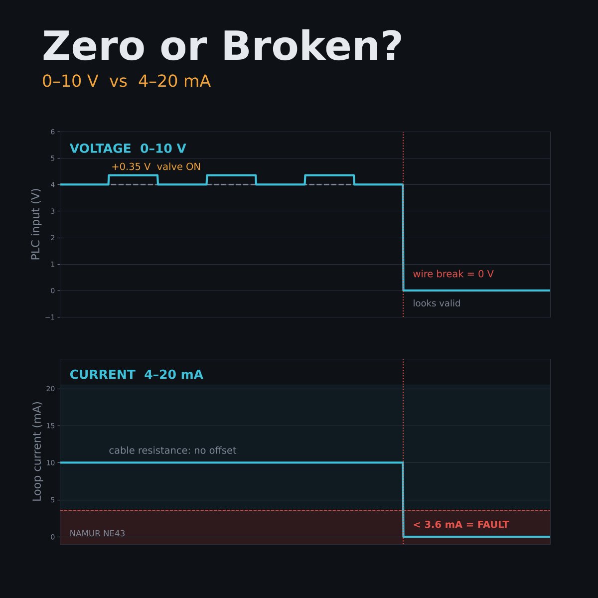
4–20 mA avoids both. Loop current ignores cable resistance within the supply margin, and anything below 3.6 mA is a fault (NAMUR NE43).
Keep 0–10 V short, inside the cabinet, with its own 0 V return.
How do you tell "zero" from "broken" on your analog inputs?
Then there's ground. Run a 0–10 V sensor 50 m on 0.5 mm² cable and share its 0 V return with a 200 mA valve. That conductor is about 1.75 Ω, so the PLC sees a 0.35 V offset: 3.5% of span, only when the valve switches.
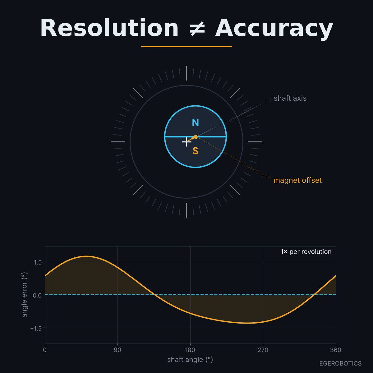
Fix the mounting tolerance first. Then linearize with a lookup table or harmonic correction.
Our magnetic rotary encoders use differential RS-422 outputs to keep the signal clean. A true angle still starts at the shaft.
A 14bit magnetic encoder gives you 16,384 counts per turn. It doesn't give you 0.02° of accuracy.
Resolution is how finely the sensor divides a turn. Accuracy is how close each count is to the real shaft angle.
#EmbeddedSystems#MotionControl#Encoder#ServoSystems#EGEROBOTICS
The mechanics decide the second one. In a TI application note, 0.1 mm of magnet eccentricity in an off-axis layout produced about ±1.5° of error. A 2° magnet tilt added ±0.4°.
This error repeats every revolution, showing up as ripple in your position and velocity loops.
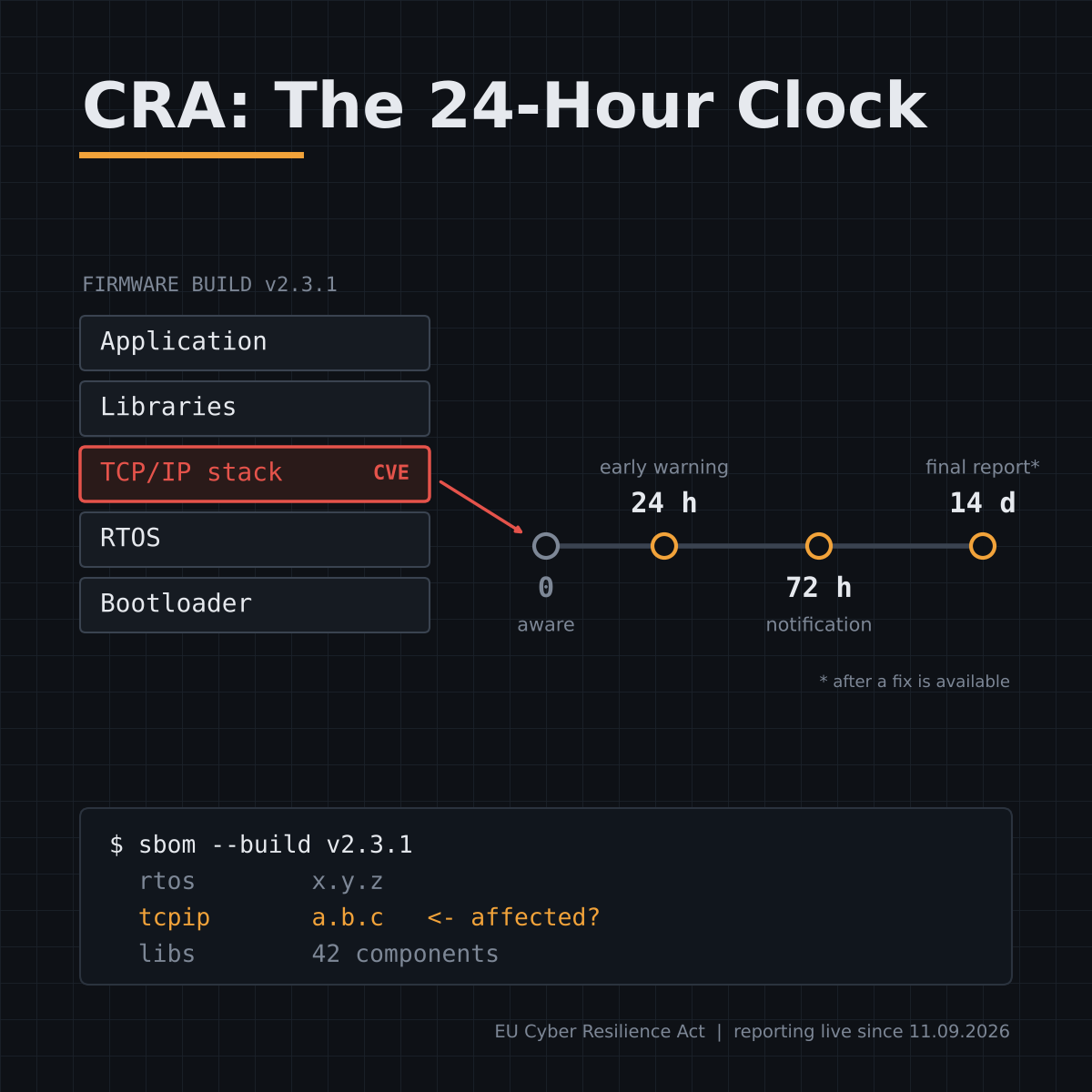
All through ENISA's Single Reporting Platform.
Products already in the field count too, even after support ends.
For embedded teams, the hard part isn't the form. It's knowing which RTOS, TCP/IP stack and library versions run in every firmware build you shipped.
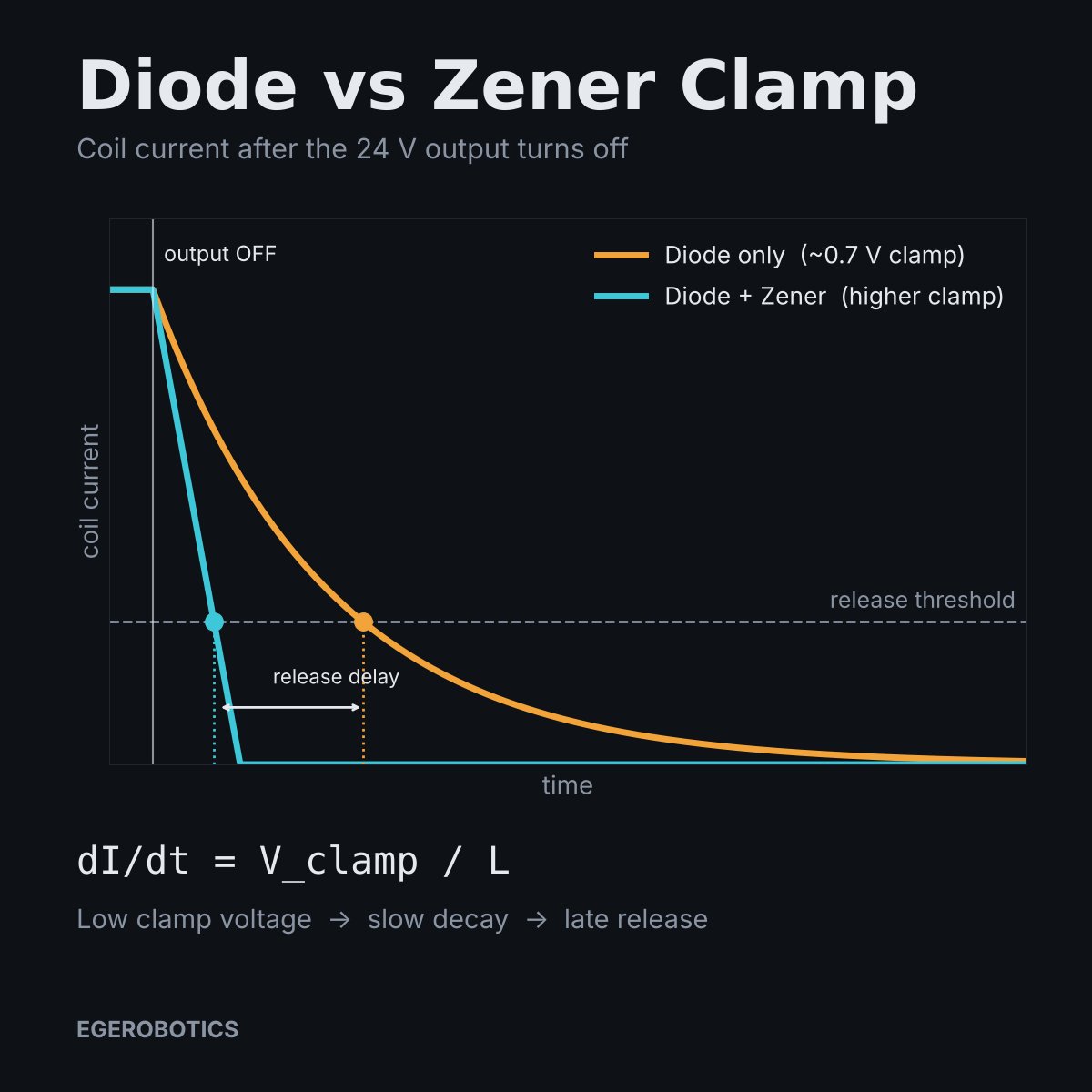
A diode plus Zener, or a TVS, clamps higher. Current collapses faster and release gets crisp. Keep the clamp voltage inside your output driver's rating.
Coil suppression is part of the timing budget.
What's on your coils: diode, Zener or RC?
The freewheeling diode clamps the coil at about 0.7 V. With so little voltage across the inductance, current decays slowly (dI/dt = V/L), and the armature keeps holding. TE notes a plain diode can stretch relay release time by up to 4x.
That's why CAM232 lets you choose G96 or G97 per tool: CSS for turning, fixed rpm for center drilling and threading.
Where do you set your clamp: per job or per tool?
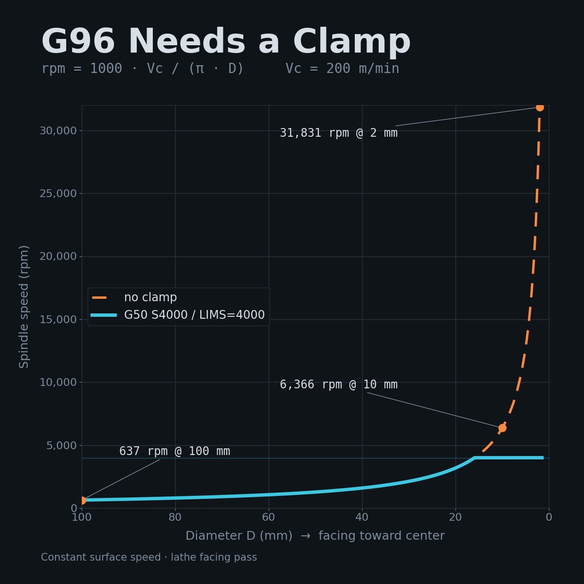
G96 on a lathe will happily try to spin your chuck at 30,000 rpm.
Constant surface speed holds cutting speed fixed: rpm = 1000 x Vc / (π x D).
#CNC#CNCTurning#GCode#CNCProgramming#CAM232
The only limit is the spindle clamp: G50 S on Fanuc and Haas lathes, LIMS on Sinumerik. Skip it, or inherit one from the last job, and an unbalanced part finds the spindle's real maximum.
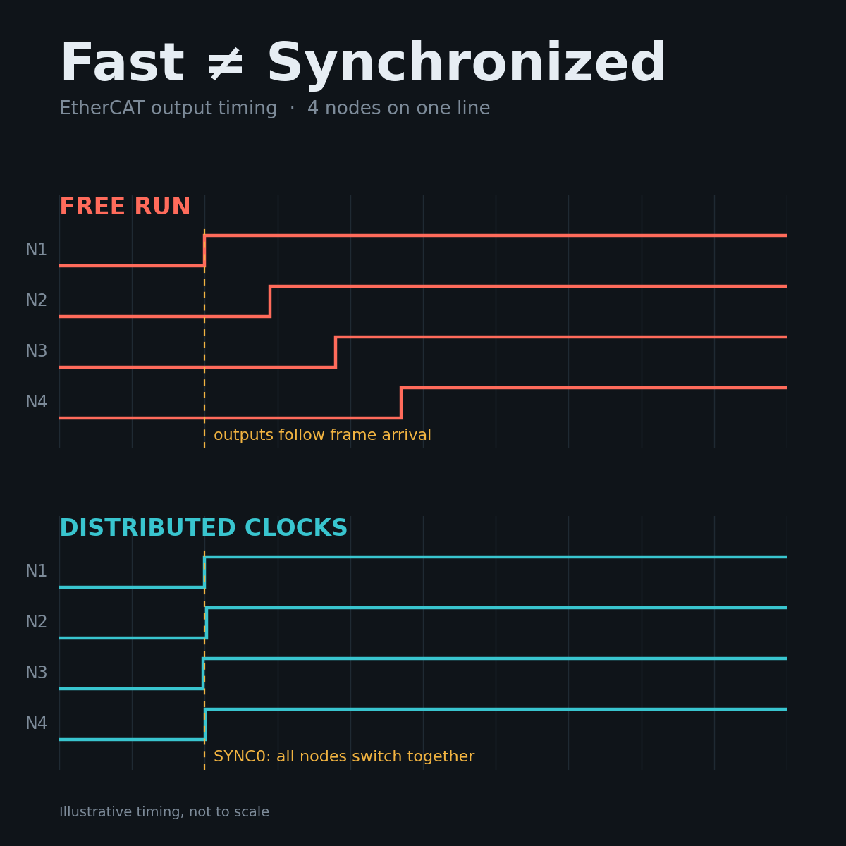
Distributed Clocks solve "when", not "how fast". The first DC-capable device becomes the reference clock, propagation delay to each node is compensated in hardware, and outputs switch and inputs latch on a shared SYNC0 event, well under 1 µs apart.