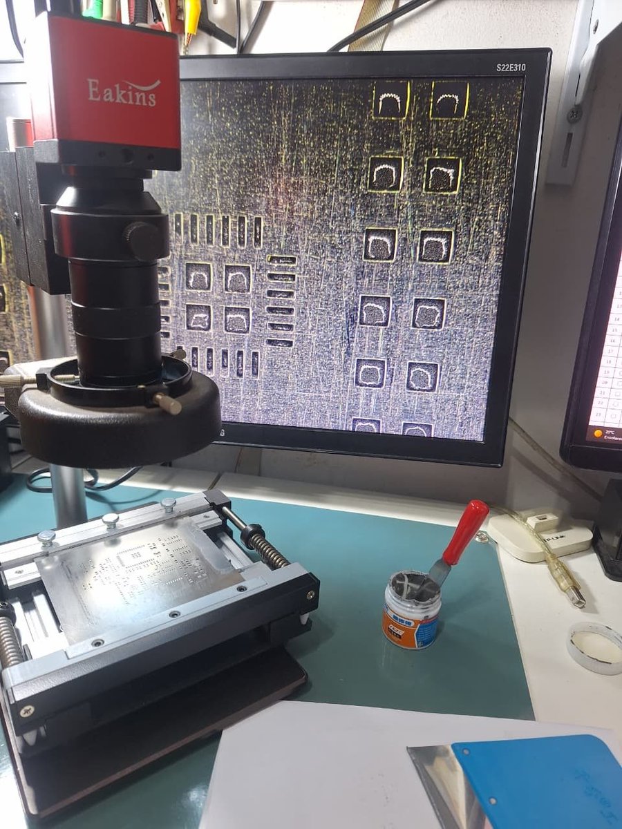
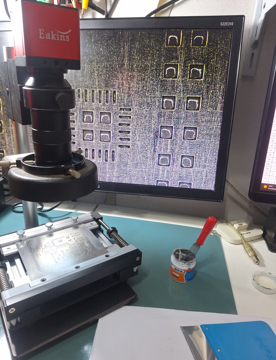
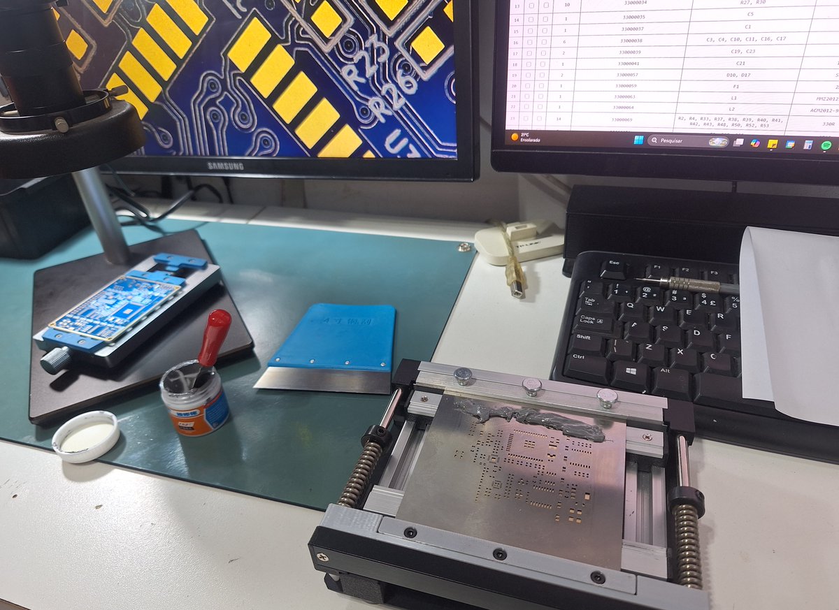
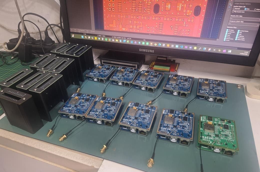
@DevDavisNunez@JLCPCB I use it to validate prototypes (1-2 pieces) and small batches (like 10-20 PCBs). Works very well. There are 8 pre-programmed profiles, and it is possible to customize some of them.
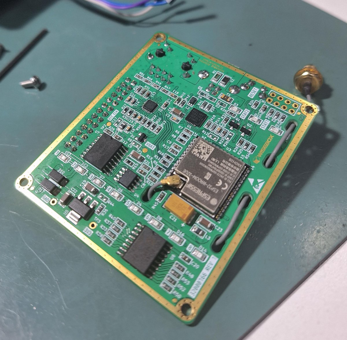
@IObrizio Is the six-pin connector in the middle of the board for firmware programming? If so, a quick tip: place it near the edge of the PCB. This allows you to use pogo pins clamp, making debugging and production much easier.
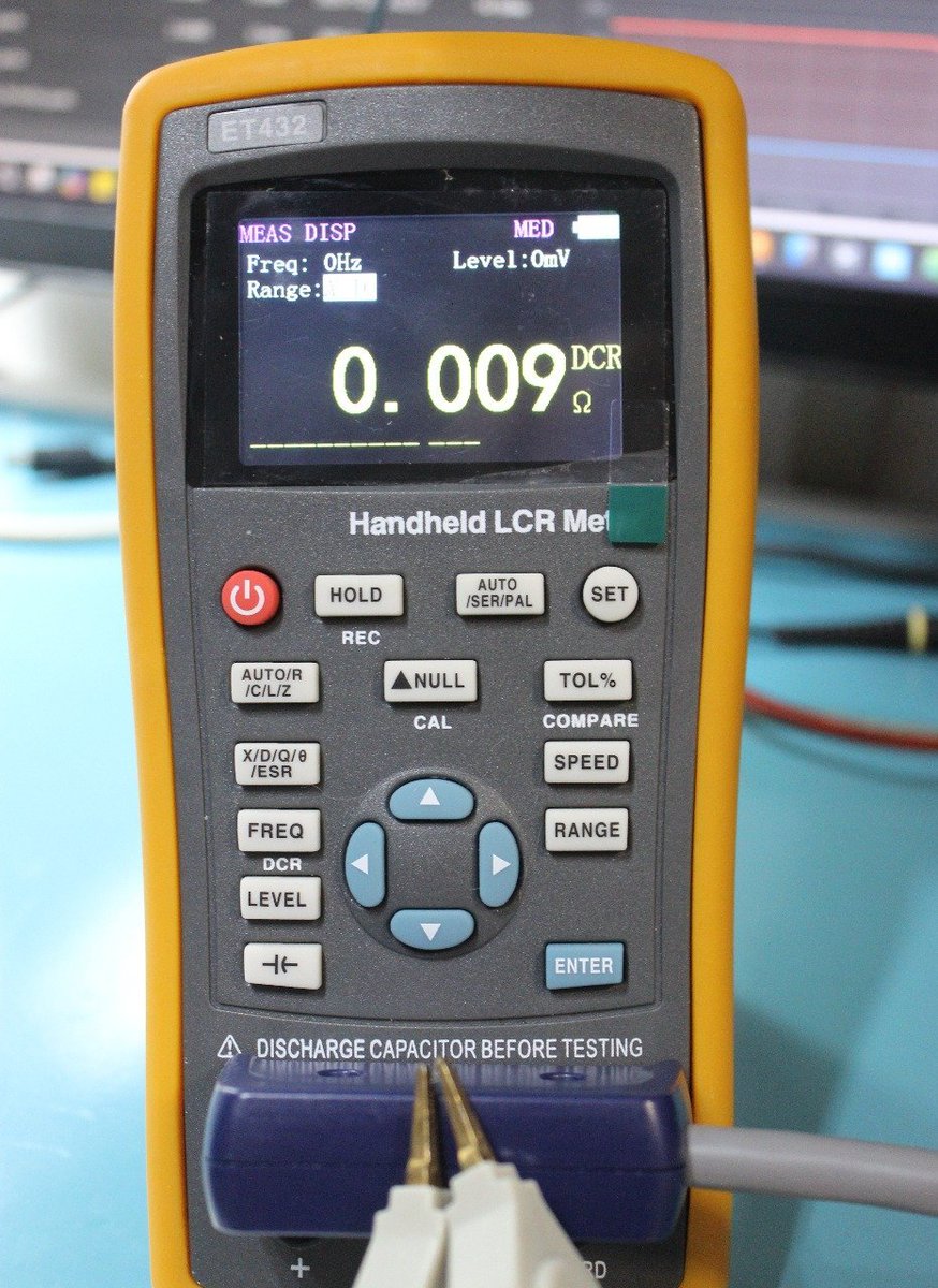
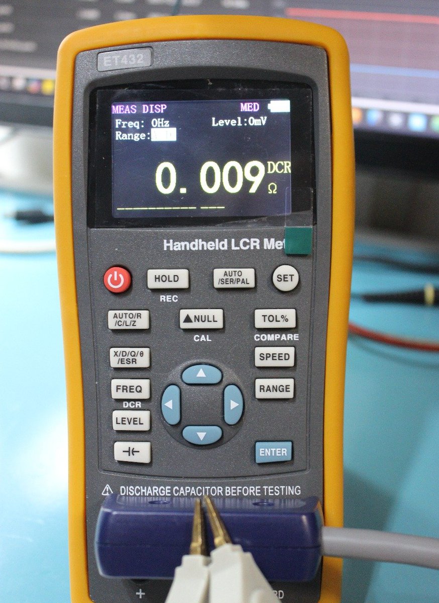
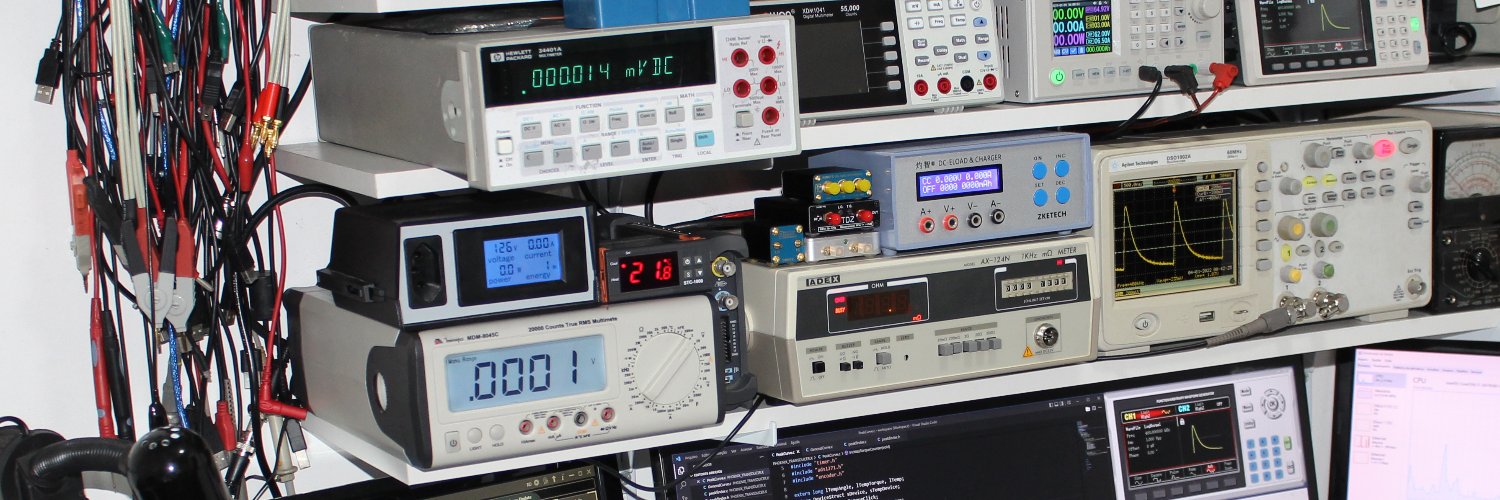
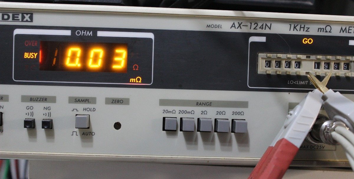
Resistance of a 1206 zero-ohm resistor measured with a milliohm meter (around 9 mOhm). With this value and the component's maximum power dissipation, it is possible to determine the maximum allowed current for safe operation. The last photo only shows the zero offset (30 µOhm).
@blind_via Resistance of a 1206 zero-ohm resistor measured with a milliohm meter (around 9 mOhm). With this value and the component's maximum power dissipation, it is possible to determine the maximum current and the number of necessary resistors. Last photo only shows zero offset (30 µOhm)
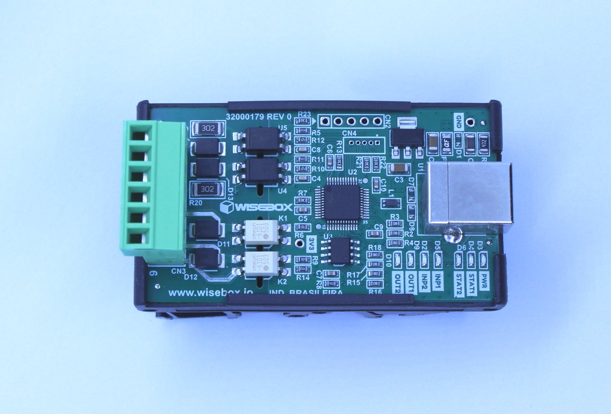
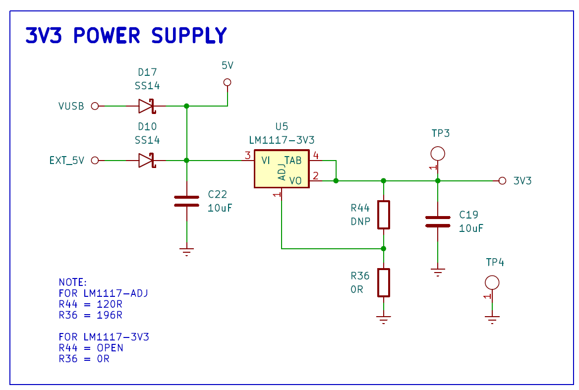
@i2cjak A zero-ohm resistor can act as a circuit configuration. It allows different assemblies using the same board. In this example, I can mount two regulator options depending on market availability. So, it gives me some flexibility.