6/ Not for large C-band weather radar (>5W per element, >100 dBm EIRP). Fits counter-UAS, tactical managed arrays, drone C2 and data links, and mobile surveillance radar in 5–6 GHz.
1/ Sparse phased arrays cut SWaP-C without sacrificing EIRP. In a dense array every active element drives overhead: beamformer ICs, RF chains, DACs/ADCs, LO distribution, thermal, calibration. Reduce element count and the savings cascade.
6/ Three optimisations in the same band because the waveforms aren't compatible. How are people handling C-band drone front-ends today: switched PA chains per mode, or one PA backed off across all waveforms?
1/ C-band on a drone hosts FPV video (5.8 GHz ISM), Wi-Fi offload (5 GHz), public safety (4.9 GHz), small SAR, and swarm mesh. Each waveform pulls the PA in a different direction: linearity, peak power, or back-off efficiency. One PA class won't cover it.
5/ H4E1N1: 4.4 to 5.5 GHz, 20W Psat, 32 dB gain, linear class-AB. For higher-power links where linearity drives the budget.
H4E1M1: 4.5 to 5.0 GHz, 20W Psat, 30 dB gain, integrated Doherty, ~32% PAE at 8 dB back-off. For OFDM/QAM data links.
5/ Integration: VDD 25V, gate bias ~-2.8V applied before drain (normally-on GaN shorts at VGG=0V), target IDQ 280mA, 50Ω PCB lines.
Part of MILLIBEAM's HEAVISIDE GaN PA portfolio. Datasheet and eval samples available.
1/ C-band carries weather radar, military radar, ISM, and satcom uplink across 4-8 GHz. Designing a separate PA for each multiplies inventory and qualification cost. H4P1G1 from @millibeam is a single 4.5-6 GHz GaN MMIC PA built to cover all of them.
4/ Unconditionally stable DC to 40 GHz, small and large signal. GaN has high low-frequency gain, so a poorly stabilised C-band device can oscillate at UHF or L-band outside the usual bench window. Critical for phased array TX modules with unpredictable load coupling.
6/ For a given EIRP target: fewer elements, smaller aperture, lower DC draw. On a drone-mounted SAR that means more flight time and more payload. What's the per-element loss budget on your current X-band array?
1/
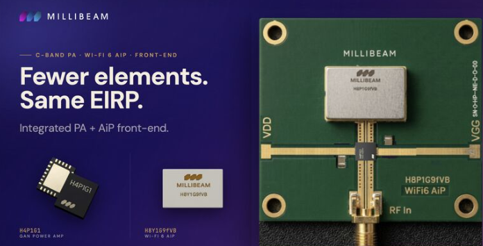
At X-band, conventional phased-array front-ends lose ~2.5-3 dB between the PA and the antenna through transmission line and connectors. Driver stages add DC consumption and heat. In a 64-element array, those penalties compound per element.
5/ Mounting the AiP directly at the PA output removes the cable and connector. The 2.5-3 dB loss at the antenna interface goes away. Each element radiates nearly twice the power of a conventionally cabled design.