@MM0OPX Inductive reactive (element is a bit too long), so the resonant point (X = 0) is somewhere below the 20m band. I would sweep the antenna from 13MHz to 14.175MHz to see where X gets to zero and look at the R again. Good stuff.
@MM0OPX I’m very interested in seeing how the feed point measurements look on the analyzer. Ideally it should be near ~100 Ohms, but stuff in the reactive near field can move it considerably. Interesting project.
@PeterVogel When I lived in San Jose, I used to fly regularly out of the Reid-Hillview airport. My instructor would jokingly say if you couldn’t read brand name of the AC unit on the top of the Eastridge shopping, you were too high for the runway 31 approach. Very very tight airport.
@seanallen_dev@seanallen_dev Thanks for being out there in the first place. I always learned something new and loved the energy in your videos. Wishing you a speedy landing at your next endeavor.
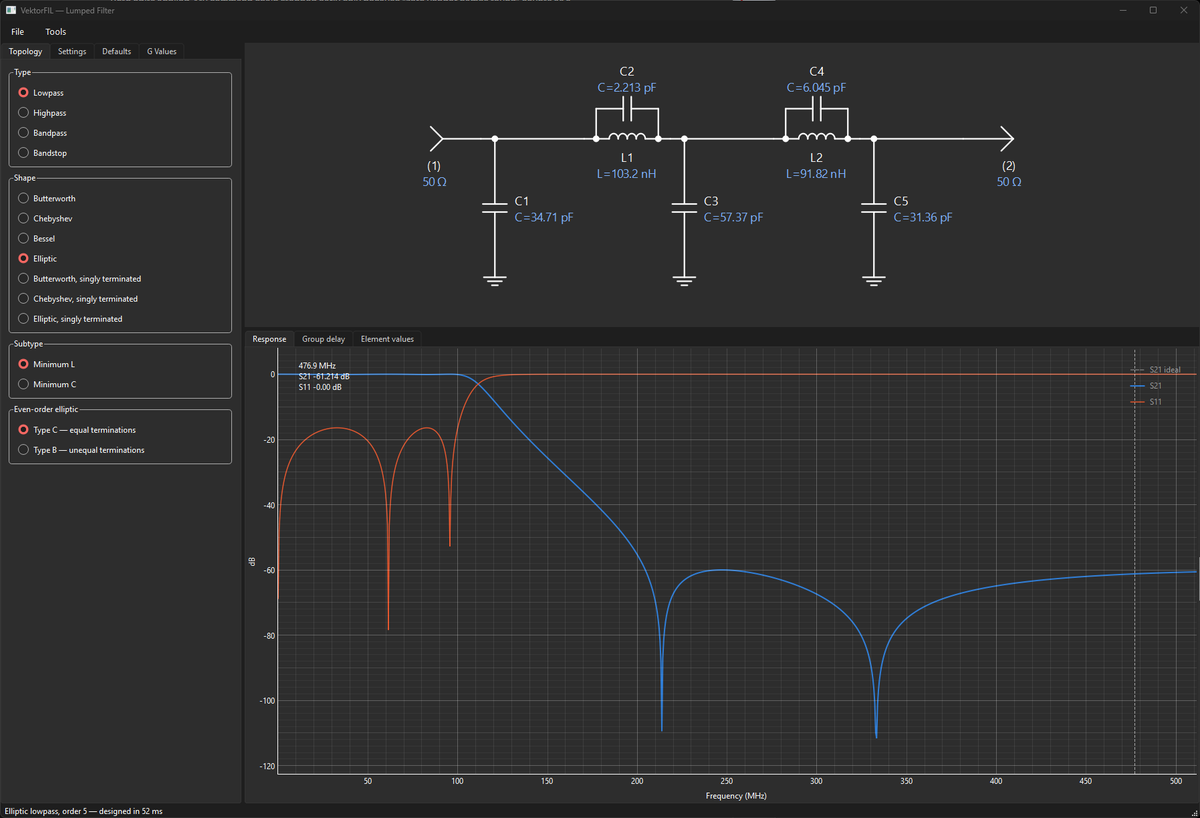
Designed my first RF diplexer in 1993 on a VAX minicomputer. Tens of millions of my plug-in filters ended up in cable HFC amplifiers and fiber nodes.
Now I’m giving the tool away: VektorFIL, free and open source. Butterworth to elliptic, coupled resonators, diplexers. Real synthesis, live schematic.
https://t.co/WgR8OGoX8N
@CaptBob_Nomadic@bscholl I would add two more things: 1) We need to get the money out of our politics. We can’t afford to have our politicians bending a knee to whomever “donated” the most money. 2) Body cams for all officials doing government business. Video evidence how our public servants behave.
@luigifcruz Really nice work, Luigi! I’m enjoying learning (or relearning) by just reading the descriptions of the Flowgraphs. Is there an example of a two-tone linearity test?