@dillonhunt1097 In many cases there is a man made signal somewhere in there from other transmissions. I don’t think you could rely on it being truly random unless you could isolate all that out.
"TV snow" is just your own receiver's electronics, not a signal from anywhere...
Tune an analog set to a channel with no station broadcasting and you get "snow," the familiar hissing field of random black and white dots. It's tempting to think of that as some kind of ambient signal being picked up, and there's a persistent bit of pop trivia that a small fraction of it is literally the cosmic microwave background (CMB), leftover radiation from the early universe. That part is true but wildly overstated as usually told: the CMB does contribute a real, measurable sliver of antenna noise power under the right conditions, commonly cited at around one percent, though the exact figure depends heavily on the antenna, the receiver and the channel tuned. Either way it's a small fraction of the total, not the dramatic "you're watching the Big Bang" framing the trivia usually gets.
The overwhelming majority of what you're seeing is much less exotic: thermal noise generated inside the receiver's own front-end amplifier, simply because any resistive component at a nonzero temperature generates a little random voltage across itself (Johnson-Nyquist noise), amplified by tens of thousands of times along with everything else the tuner is listening for. With no station present to dominate that noise floor, the amplified thermal noise is all that's left to display, which the demodulator renders as the random dot pattern. It's a nice reminder that even "nothing" on an analog receiver is still showing you something real, just not a broadcast.
By the way, why monochrome? With no station there is no colour burst, the colour killer turns chroma off and snow is grey. I've mentioned colour killer in previous posts.
"White" on a black-and-white TV was never one chemical...
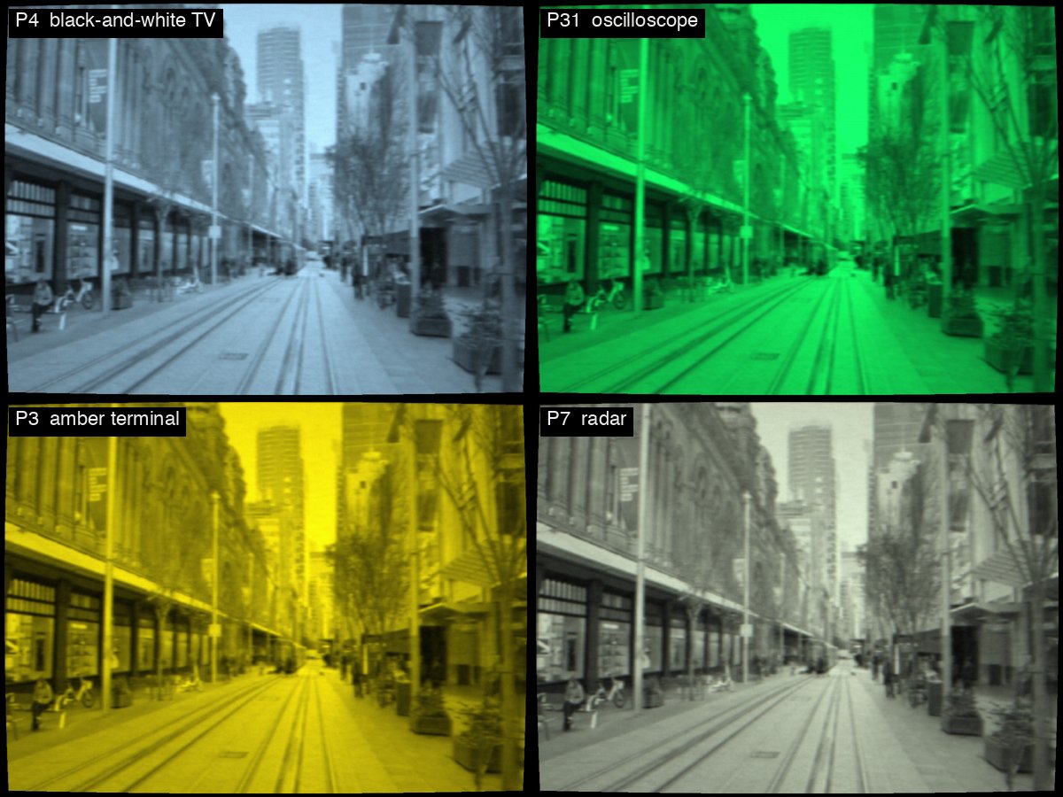
Every CRT's picture comes from an electron beam exciting a phosphor coating, but "phosphor" was never a single standardized substance, it's a whole family of formulations chosen for different display purposes, each with its own colour and its own persistence (how long the glow lingers after the beam moves on). Monochrome broadcast television used P4, and P4 isn't a white-emitting compound at all. It's a blend of two powders, a silver-activated zinc sulfide that glows blue and a zinc-cadmium sulfide that glows yellow-green, mixed so the two outputs add up to something the eye reads as white. A slightly cool white, in fact: RCA's measured colour for P4 is a touch bluer than daylight. There's no shadow mask involved and no colour filtering going on, which there can't be on a monochrome tube. It's just two powders chosen so their sum lands where you want it.
Other applications picked completely different phosphors for completely different reasons. The familiar oscilloscope green is P31, a copper-activated zinc sulfide, and it was not chosen for long persistence, which is the thing people usually assume. P31 decays fast, to a tenth of its brightness in a few tens of microseconds by RCA's figures, much like P4. What it has is efficiency: it's very bright for the beam current you put in, and it resists burning, which is what you want on an instrument that spends its life displaying the same trace.
If you actually wanted a trace to hang around after the beam had gone, you reached for something like P7, which is genuinely two layers rather than a blend: a fast blue-white flash on top of a slow yellow-green layer underneath that keeps glowing for seconds. That's the radar-screen phosphor, and the reason a radar sweep leaves a trail behind it. Amber terminals used P3, slower than P31 and with almost no blue in it, which is the part people found easier to stare at all day. Same basic tube mechanism, different chemistries, different jobs.
If you want to go down the rabbit hole of phosphors, check out the Wikipedia page here: https://t.co/itBLUArf9n
We are slowly adding new phosphors to the AnalogTV simulation and they are all modeled on the underlying chemical properties and historical documentation.
@jbaker_graphics I was on the same journey as you trying to learn about the best way to do this. Although AnalogTV doesn't use any code from these projects, check out some of the inspiration here: https://t.co/T3pB3WZewp
In particular ntsc-rs is a fully 1D implementation.
Flagging. If you rented a lot of tapes you will have seen this. The picture is fine except at the very top, where everything vertical leans over sideways, a lamp post or a door frame hooking off like a flag on a pole, and the bend sways back and forth while you watch. It goes by flagging, or flag waving, and Sam Goldwasser's VCR repair FAQ gives the everyday cause in one line: "low backtension will usually show up as a waving or flagging effect at the top of the picture."
The odd thing is that the tape does not bend anything. A VHS deck reads each field from its own diagonal track, using one of two heads on a spinning drum, and hands over from one head to the other once per field. An RCA patent filed in 1977 explains what goes wrong at that handover: "slight differences in tape tension or in the dimensions of the mechanical tape transport acting on the tape for playback compared with the tension and dimensions when the tape was recorded results in differences in the time between succeeding horizontal synchronizing pulses". The horizontal timing jumps, and the jump "normally occurs about five horizontal lines before the end of a vertical scanning interval".
That puts the jump inside the picture, in its last few lines, and it is the other half of the same fault. The torn strip at the very bottom of a VHS picture, usually called head switching noise, is the jump itself, drawn before anything has had time to react. A television normally hides those lines in its overscan, which is why you remember the top of the picture misbehaving and not the bottom.
The top is the television catching up. A set keeps its horizontal scan in step with a loop that is slow on purpose, so that noise on a weak signal cannot shake the picture about, and RCA says its filter will "normally prevent the controlled oscillator from changing at a rate great enough to readjust itself before the end of the vertical blanking interval." So the catch-up spills into the next field, and a JVC patent filed in 1976 says where it ends up: the bending "continues also in the initial part of the next field succeeding to the blanking period, that is, the upper part of the picture screen."
It does not glide back cleanly either, which is why flagging tends to look like a ripple rather than one neat curve.
Which way it bends depends on which way the timing jumped, and RCA's wording covers both, so flagging leans right on one tape and left on another. The jump is only as big as the timing error at the handover, and when the tension drifts, the error drifts and the bend swings with it. That is the waving.
It was also blamed on televisions as much as on tapes. A 1985 patent notes that "Both flagging and skewing problems (visibly) occur mainly on the older type television receivers", and the fixes went into sets. RCA's patent describes an earlier one with "an external switch by which the user may change the characteristics of the low-pass filter in the phase-locked loop when using a tape recorder", and both RCA and JVC went on to make the loop fast only during the vertical interval, because, in JVC's words, "the vertical blanking period does not appear on the reproduced picture screen even if there is noise".
The names were never tidy, for what it is worth. That 1985 patent keeps "flagging" for a different cause, the two heads not sitting exactly 180 degrees apart on the drum, and calls the tension version skew. Both put a timing jump at the same handover, which is why the words blur.
The clip is a Sydney street shot recently on iPhone but played from AnalogTV's simulated VHS tape on a CRT set, with the Flagging control in AnalogTV's VCR tab at 0.7. It follows the same chain: the control sets the size and direction of the jump at the head switch, the last five lines of the field take the whole jump, and the simulated set's loop catches up with an overshoot. How fast that loop is and how much it overshoots are our choices, because none of our sources give figures; though we have live samples from real tapes that we try to model. The torn bottom lines are there too, but our simulated overscan hides them, as a real television's would.
@jbaker_graphics On your point about not having a mac device to try it on, I'm waiting until AnalogTV is "feature complete", the simulation engine is improved and the UI looks much nicer. Once that's done, I'll embark on a Windows and/or Android and/or WebGL version.
A CRT is a vacuum tube, which means the glass envelope has to hold back roughly one atmosphere of pressure pushing in on every square inch of the faceplate, over a thousand kilograms of total force on a typical set's screen. A dome shape distributes that load far more evenly than a flat sheet would, which is the actual engineering reason early CRT faceplates were noticeably spherical rather than flat, not a stylistic choice.
The tradeoff is geometric and has two main consequences:
First, sweeping a beam at a constant angular rate onto a screen that is flatter than that sweep wants produces pincushion distortion, edges pulled inward, which is why many sets carry pincushion correction circuits and why service manuals have adjustments for it.
Second is the barrel look people associate with old TVs. This is the physical bulge of the glass itself, which bows straight lines outward when you view or photograph the tube face. Corner vignetting comes along with the curvature too, since the beam travels further and strikes at a steeper angle at the corners than at the centre.
Manufacturers spent decades chasing flatter faceplates, thicker glass and better internal bracing to reduce the curvature without the tube failing structurally, culminating in genuinely flat-screen CRTs like Sony's FD Trinitron in the late 1990s, right before CRTs themselves were phased out entirely. Every step of that "how flat can we make it" progression was really a materials and structural engineering problem wearing a picture-quality feature's clothing.
I’ve been messing with TV tech since I got my first Newvicon camera in 1984 and then joined the local Public Access Cable channel to user their ‘real’ equipment. My career path took me in a totally different direction, but I still love collecting and playing with video gear as a hobby. The app itself stems from a COVID-era idea I had for a universal TV equipment simulator. As a ham radio person, the rise of SDRs meant that this was more and more possible, then with the power of smart phones, it’s become something you can carry around with you.
@lastaut2 They did indeed. Our app models some of the phosphors that were used for the monochrome displays. Eventually we hope to model all the phosphors that we can find out about. There is a neat list of them here: https://t.co/wIokwlFuOU
NTSC colour was designed so your grandparents' black-and-white set wouldn't notice
When the US adopted the NTSC colour standard in 1953, there were already tens of millions of black-and-white sets in American homes, and nobody was going to replace the entire audience's hardware overnight. The standard was built around strict backward compatibility instead: the colour subcarrier is placed at a frequency, 3.579545 MHz, chosen so it falls between the harmonics of the line rate and interleaves into the existing luma spectrum with minimal visible disruption on a set that doesn't decode it.
But "minimal" isn't zero. On a black-and-white set the subcarrier still reaches the tube as a fine dot pattern in the picture, most visible on the saturated colour bars and title cards broadcasters loved to use. The sets already in people's homes had nothing to remove it, and they didn't need anything: the subcarrier's phase flips from one frame to the next, so each frame's dots land where the previous frame's gaps were, and the eye averages the pattern toward plain grey. Some later black-and-white sets added a chroma trap anyway, a notch filter tuned to 3.58 MHz that takes the subcarrier out of the picture signal before it reaches the tube, and colour sets have to strip it from the picture signal too, with a trap or, in later sets, a comb filter. The clever part of the standard is that the sets people already owned didn't need a single modification.
This is a frame of an NTSC colour signal (SMPTE colour bars) shown on an AnalogTV simulated B&W display (P4 phosphor, no mask) with no trap (i.e. TV sets in homes in 1953) vs with trap (i.e. more 'modern' B&W TV sets)
Philips introduced the Plumbicon in 1965, a camera tube using a lead-monoxide photoconductor instead of the antimony trisulfide target found in earlier vidicon-family tubes. The material change made a huge difference: Plumbicons had dramatically lower lag (image retention from frame to frame) and were far more resistant to burn-in from static bright content than the tubes broadcasters had been using.
Lower lag meant camera operators could pan and follow motion without the smeared comet-tails that plagued earlier tube types, and better resistance to burn-in meant a camera could be pointed at a bright studio light or a static test card without permanently marking the target. Those two improvements, more than any single dramatic feature, are why the Plumbicon became the standard broadcast colour camera tube through the 1970s and into the 1980s, quietly present in most professional 3-tube colour cameras of that era, with the Saticon as its main rival from the late 1970s, right up until CCD sensors took over.
The video sample is a side-by-side comparison of Vidicon vs Plumbicon as simulated in the AnalogTV app. The values are sourced from Hamamatsu datasheets for the Vidicon and from the Mullard 1987 datasheet for Plumbicon.
We think it is :) - Check it out at https://t.co/dmIOhhnCYb and if you have a Mac, iOS device or even an AppleTV there is a version for you. The simulations we post about are generally from the Mac or iOS version with the AppleTV version mostly for people to view their own content on a TV through the simulation.