Soft-/firm-/hard-/gate-ware consultant @ Merulogic Oy during the day, hardware research and emulators in evenings.
Game Boys, Rust, husband, alopecia patient
I'll probably stop being active here, but you can find me on the popular B and M alternative apps 😀 I'm verified on both using my personal domain https://t.co/ppdUQmMXQC
Instructions are here: https://t.co/T7OmrK71Jy
GBA carts that have a soldered battery obscuring the ROM chip are a bit more complicated, because one photo is required where the battery has been desoldered. Sorry!
After a long break, I'm opening the cartridge section of https://t.co/B0sfiwJmBd once again for new submissions! I've added almost all GB/GBC/GBA games to the list and most have no submissions so it's looking a bit empty 😅 You can help by taking photos and sending submissions!
@JaceCear ROM dump info *is* shown if it's included in the submission, but dumping is not a requirement because not everybody has a dumper (but everybody has a camera/smartphone). My own Wario Land 4 submission currently omits the hash because I'm lazy, but I'll add it soon 😅
The Game Boy Hardware Database now contains a GBA cartridge section 🎉
https://t.co/cdB2BEKk7A
Only a few entries right now but more are coming! Submissions are still officially closed but I accept them from some known good contributors whose submissions require minimal work
"Two schematics releases on the same day? Surely you jest, Gekkio!"
Schematics for the Game Boy 4-player adapter:
https://t.co/z0dg4JEt4N
Nothing special since Jeff Frohwein's old schematics are already available, but my release also includes unpopulated board photos
Exactly 0 people have requested this one but I reverse engineered it anyway: Game Boy Light DC/DC converter board (LSEP01120A1) 😁
Schematics are here:
https://t.co/dom0eY7dck
The previous photo showed only the central area where all the interesting logic is. I've already identified all the pins, labeled here in a photo showing the entire chip. Some pin functions are still a mystery since RE work on the logic is not yet finished
An old RE friend/adversary: MBC3B memory bank controller found in some Game Boy cartridges
Relatively modern tech (approx. year 2000-2001) so it's tiny, and limits of optical microscopy are making things difficult. Also: a ton of connections obscure the cells underneath
@zwenergy0 It's fast (<1s feedback loop to render a PDF while writing), mostly very intuitive, composable (easy to reduce repetition by making reusable parts), and modern (UTF-8, watch mode, incremental compilation, etc...).
I predict it'll end up replacing both LaTeX and LyX in my toolbox
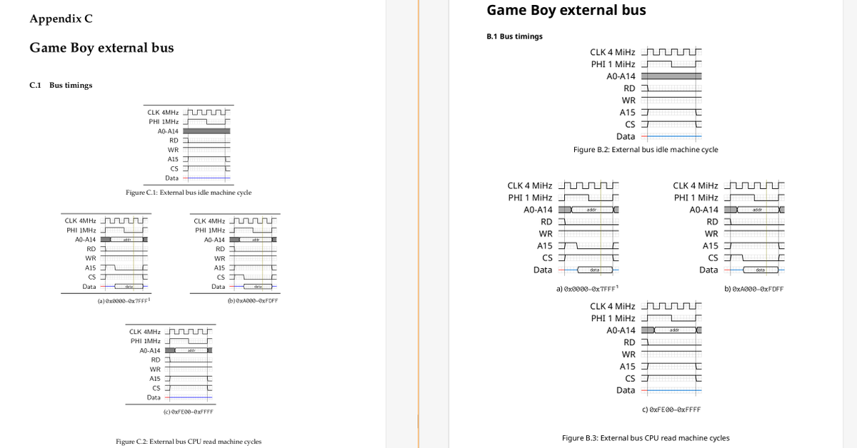
Working on migrating gb-ctr (https://t.co/48VBRBmm6j) from LaTeX to typst in order to write more docs easier. Had to write a tikz-timing equivalent for the timing diagrams, and it's starting to look pretty good! Left: LaTeX, Right: typst. Not perfect 1:1 match but good enough
@qwertymodo Oops, I need to fix that note 😅 And yes, I've got a R-01 sent by you, and it looks like I never submitted that to gbhwdb...I really should add it ASAP since that's the only version missing.
Time for yet another Game Boy schematics release!
It's something I started working on way back in 2018: Super Game Boy!
Fully traced SGB-R-10 board SVG + schematics that hopefully cover all SGB board revisions (assuming I spotted all the differences!)
https://t.co/WctPi9pljc
@felipehertzer Not right now, because leaked schematics exist so my version wouldn't be *that* useful. But I'm slightly interested in making schematics for CGB-CPU-06 / CGB E, which has some important differences to the other versions.
Here's my latest schematics release: original Game Boy (DMG)
https://t.co/cOWfc3GybO
Some DMG schematics can already be found on the internet, but they lack some details, have errors, and/or in my opinion have some quality/readability issues.
So here's my take on it...enjoy! 😄
@TommyBurazin Sorry, I don't have exact details but my notes suggest the size might be SMA and I don't think any special specs are needed. I wouldn't be surprised if pretty much any replacement of same size would work. Something like forward current >= 1A, reverse voltage >= 20V
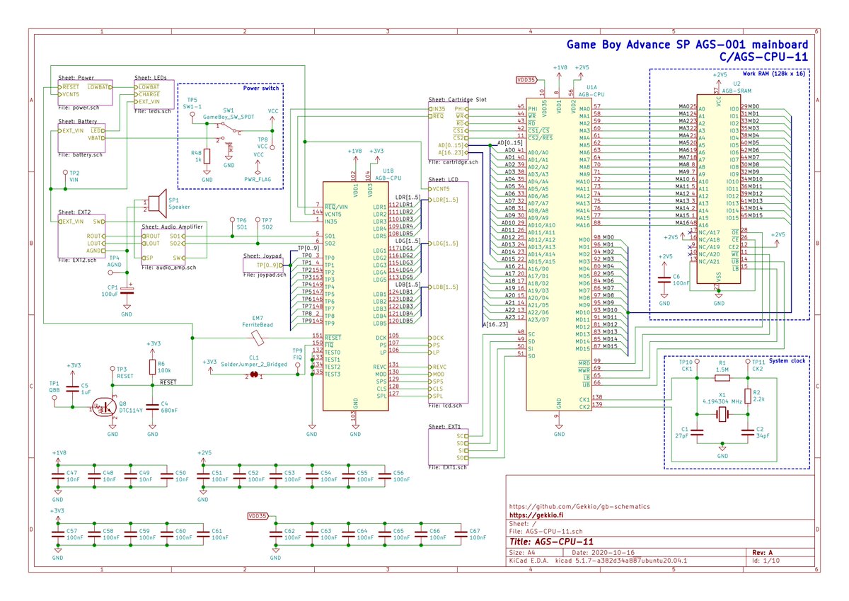
After another evening of lovely reverse engineering work, I proudly present the first publicly available schematics of Game Boy Advance SP console.
(this is for AGS-001 mainboard revision AGS-CPU-11...other versions have some differences)
https://t.co/GRcgCuPHS7
I should use the word combatible more often
"Device is compatible with Linux" = it works / should work with Linux
"Device is combatible with Linux" = if you use Linux and fight really hard, possibly losing brain cells / part of your soul in the process, you might get it to work
Current status: trying to untangle this embedded RAM logic from Game Boy MBC2 (Memory Bank Controller) chip 🤔
I've done maybe 98% of the schematics for the MBC2 chip already, but still need to understand some things to verify my schematics are correct.
@qwertymodo Thanks for the info! My hunch is it's not needed if the clock source is near ICD2 but I don't think it's harmful either..however, I don't 100% understand why it's there in the original 😅 I'll do some probing and document the original circuit in my SGB schematics as well as I can
@qwertymodo
Thanks for the ICD2 clock notes on your Super Game Boy Clock Mod page! However, I'm confused about why AC coupling is needed.
I'm asking because I'm almost ready to release my schematics of SGB (and soon SGB2) but would like to fully understand the circuit first...
I know full 5Vpp ~21 MHz can be problematic but don't understand if the problem is in the ICD2 side (e.g. voltage level reqs, too much pin/trace cap/ind) or driving end (e.g. poor slew rate). You've done more SGB research than me so I hope you might know why Nintendo did this 😄