@BcoBolivariano También tengo problemas con la app y con el sitio web. Traté de ingresar un reclamo para dar más detalles pero no tienen opciones para reportar problemas con la app.
@CNEL_EP En mi sector (La Milina, Salinas), estamos experimentando variaciones de voltage. Algunos vecinos incluso no pueden mantener encendida la refrigeradora por lo que hay temor a que se dane o que nos quedemos sin energía como ocurrió el fin de semana @CNEL_EP .
NEW VIDEO! Upgrading our WORST Setup
https://t.co/wkqzTPw7Bf
#Sponsoredby#nvidia
To win your own 4080 Super use the link below: https://t.co/3SBZFCYUID
At 14, Anton received an old laptop that changed everything. Now he’s using AI to help himself and others achieve their potential. https://t.co/bOLgVscCEO
So after a four try and error, I think the case is stable now.
Long story short: The core issue designing the enclosure (for me) is that during the PCB layout there isn't much space at the first place such that I have buttons, encoders, connectors almost around the enclosure. Which I have to make sure the PCB can assemble into the box too.
During the PCB layout, I do have in mind of those components placement, but once you miss the details, it will cause the pain on the case design.
There are two details I missed: HDMI connector and button placements:
For HDMI, the connector is extruded from the PCB edge which is normal for these connectors, but because I want to slide the connector cover into the enclosure this means I need to have a cut out on the 3D printer build plate side, which increase the difficulty to print. Not to mention that under that HDMI connector, there is a QWIIC connector that doesn't have thick walls either, which makes the cutout even more difficult.
On the other hand, the button placements for CFE card ejector and power button is also a pain for case design, because the button will be extruded from the PCB edge too, I need to assemble the PCB with an angle, but because it is placed around a corner and 90 degrees apart, the angle I need has limited range that I need to cut some space in the enclosure to ensure the PCB have enough wiggle room.
So this is definitely a learning experience for me that if I'm designing future project with similar complexity, enclosure design should be parallel with the PCB design too. I underestimate the challenge.
Other then that' I'm very happy with the result and my trusty Prusa MK3S+, even I divide the case in to three parts with a sliding plate, the dimension are pretty precise and after assembly, it really looks like a same piece. I'm also glad how the button cutout and the LED indicator passthrough turns out.
Will put this on Github later along with the PCB files.
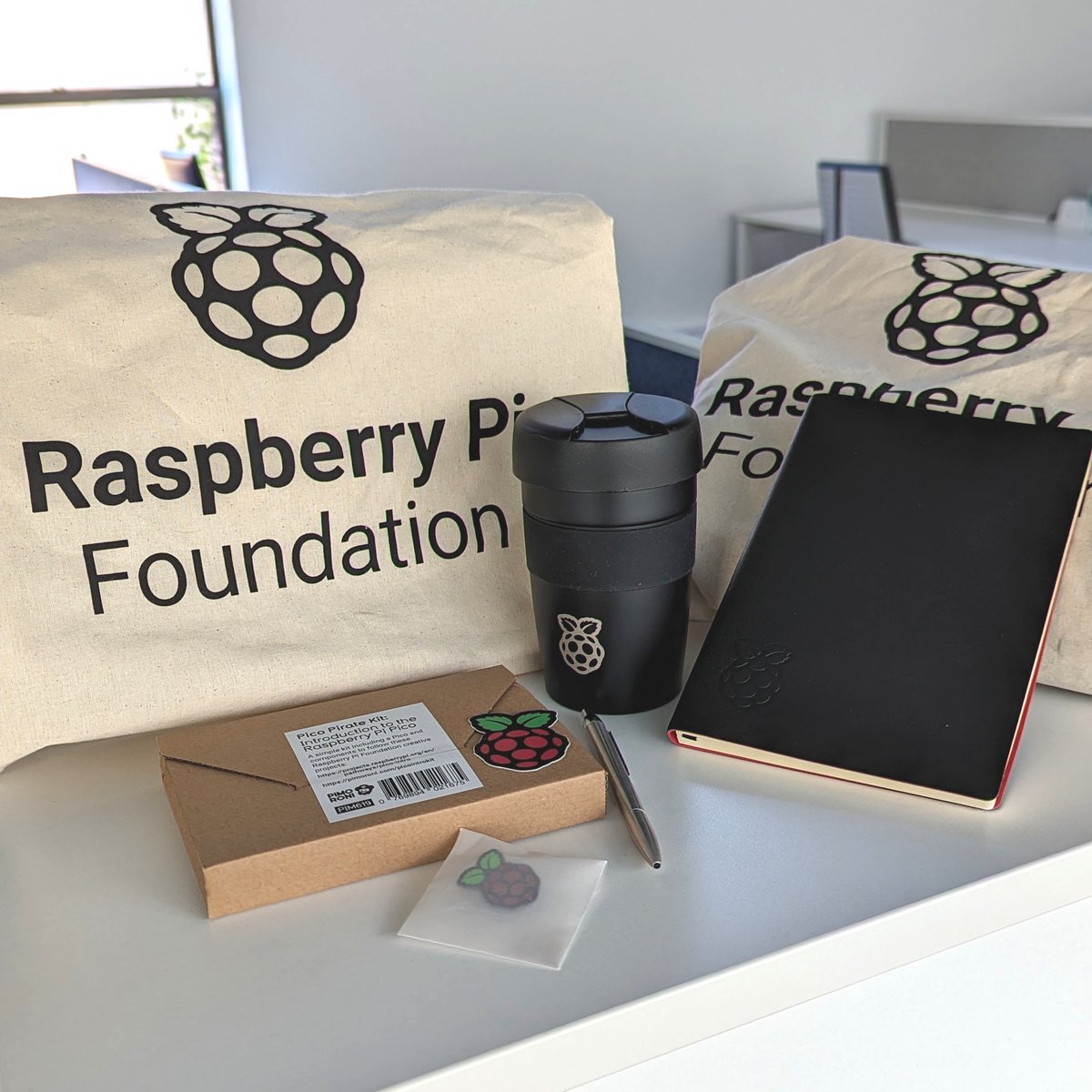
10K FOLLOWER GIVEAWAY 🎉🎈🎁
To celebrate 10K followers on Twitter, we're giving away 3x Raspberry Pi Foundation tote bags containing Raspberry Pi branded goodies 😍 Winners will be randomly selected on Friday, 19 May 2023.
To enter: Follow us, like & RT this tweet.
Good luck!
🌋 #Guayaquil | Imágenes publicadas en redes sociales captan al volcán Chimborazo desde el Puerto Principal, esta mañana del 26 de abril de 2023.
Más detalles 📲 https://t.co/WI4pdwHGlh
@servicioscnelep Durante la madrugada de hoy nos quedamos sin luz en La Milina, #Salinas, por El Faro. Intentamos reportar por teléfono pero se cuelga la llamada luego de esperar turno
If you care about your Java developer friends, ping them about #log4j today. Called a dev friend, he had no idea about it & thought he was supposed to wait for the company's annual pen test to flag for upgrade