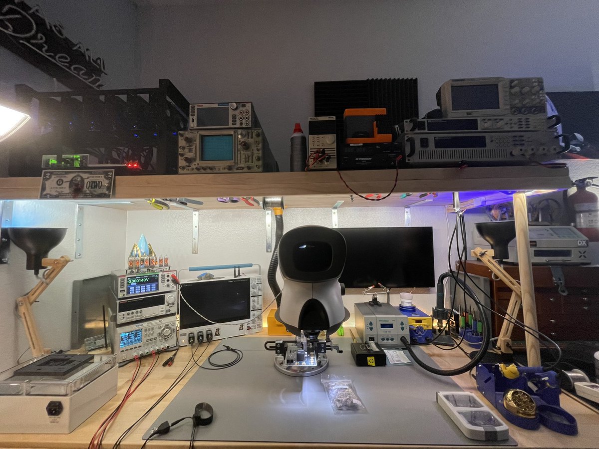
show me your home lab!
“What’s your choice for a single best aid to an interesting and productive circuit design career? A PhD? An IQ of 250? A CAD workstation? Getting a paper into the Solid State Circuit Conference? Befriending the boss? I suppose all of these are of some value, but none even comes close to something else. In fact, their combined benefit isn’t even worth a fraction of something else. This something else even has potential economic rewards. What is this wondrous thing that outshines all the other candidates? It is, simply, a laboratory in your home. The enormous productivity advantage provided by a home lab is unmatched by anything I am familiar with. As for economic benefits, no stock tip, no real estate deal, no raise, no nothing can match the long-term investment yield a home lab can produce. The laboratory is, after all, an investment in yourself. It is an almost unfair advantage.
The magic of a home lab is that it effectively creates time. Over the last 20 years I estimate that about 90% of my work output has occurred in a home lab. The ability to grab a few hours here and there combined with occasional marathon 5-20 hours sessions produces a huge accumulated time benefit. Perhaps more importantly, the time generated is highly leveraged. An hour in the lab at home is worth a day at work.
A lot of work time is spent on unplanned and parasitic activities. Phone calls, interruptions, meetings, and just plain gossiping eat up obscene amounts of time. While these events may ultimately contribute towards good circuits, they do so in a very oblique way. Worse yet, they rob psychological momentum, breaking up design time into chunks instead of allowing continuous periods of concentration. When I’m at work I do my job. When I’m at home in the lab is where the boss and stockholders get what they paid for. It sounds absurd, but I have sat in meetings praying for 6 o’clock to come so I can go home and get to work. The uninterrupted time in a home lab permits persistence, one of the most powerful tools a designer has.
I favor long, uninterrupted lab sessions of at least 5 to 10 hours, but family time won’t always allow for this. However, I can almost always get in two to four hours per day. Few things can match the convenience and efficiency of getting an idea while washing the dishes or putting my son to sleep and being able to breadboard it now. The easy and instant availability of lab time makes even small amounts of time practical. Because no one else uses your lab, everything is undisturbed and just as you left it after the last session. Nothing is missing or broken, and all test equipment is familiar. You can get right to work.”
- Jim Williams “The Art and Science of Analog Circuit Design”
@leahy30xy@fuzziphy@haydendevs hah this is a cool idea! i may try it on paper with my kids (over many days)
how many dice rolls before it starts to take shape visually?
@furt_tech@LorenCharnley@blind_via would need to see it. what is max i_out on the pass thru? what is vout and the load on the buck? what exactly is the issue you’re having?
yeah i would imagine you'd want to interface agnostically with the standard output formats from these tools (gerbers, IPC netlists, ODB++, etc)
one thing i'd like to see is both automated test plan generation as well as write all the test software. this is something that i think is well in the capability of LLMs with a slight amount of human guidance.
>tools that help with component libraries (sym/footprint generation, part data)
>schematic review potentially, although this is still a dangerous one because it misleads almost as often as it's helpful (esp these flybynight websites that just are a wrapper that throws your schematic into claude or gpt)
>anything related to the documentation around design (specs, test plans, DFMEAs, regulatory stuff)
>basically the boring/secretary type work that is a large part of PCB design, but not actual design. AI lends itself to these tasks today and many people are just spinning up their own tools to handle this.
>routing a PCB is just a hard problem computationally, it's like drug discovery/protein folding kind of compute. LLM is not the right tool for this. RL seems to be failing too.
>design can be augmented by LLMs, but again, this is more on the research and documentation side, CSWAP tradeoff analysis, supply chain stuff... a human still needs to be at the wheel, the LLM is just doing handling the dull stuff
@LorenCharnley@blind_via@furt_tech agree, voltage can be split or routed even, but generally each signal should have one continuous adjacent reference...
especially today where parts have risetimes that are sub 1ns and the cost of multi layer quality fabs are generally no where near the top line item of a PCBA.
i wouldn't think so. if the 50 hz is actually in the rf signal path, filter it deliberately with a passive or active filter.
if it's common mode pickup, use diff signaling, a balun, cmc, shielding, etc... cutting up the return plane is more likely to create return path discontinuities than to address root cause.