Forging precision work Used Machine China supplier🇨🇳🇨🇳🇨🇳 Shipping Worldwide Exporter🚢🚢🚢 We are from China and we are a supplier of second hand machine tools
At High Frequencies, a Capacitor is No Longer Just a Capacitor.
If you work in RF or high-speed digital circuit design, you quickly learn a harsh truth: selecting a capacitor is rarely about the capacitance value on the label. Instead, it’s about managing the component's parasitic behaviour.
In high-frequency environments, a real-world capacitor transforms into a complex RLC series circuit. If you don't account for this, your circuit will suffer from unexpected heat, power loss, or even complete signal inversion.
Here is a quick engineering guide to mastering high-frequency capacitor selection:
1. The ESR and ESL Trap
* ESR (Equivalent Series Resistance): Generates unwanted heat and power / signal loss.
* ESL (Equivalent Series Inductance): Created by physical leads and internal structures. At ultra-high frequencies, ESL dominates, causing the capacitor to behave like an inductor.
* The Rule: Choose components that stay firmly in their "capacitive region" across your target operating frequency.
2. Dielectric Matters: The RF Hierarchy
Not all ceramic capacitors are built equal. Your choice of dielectric dictates stability:
* C0G / NP0: Ultra-stable over temperature/voltage with low loss (High Q). * Use for: Tuning circuits, filters, and precision timing.
* X7R: Decently stable. *Use for:* General-purpose decoupling.
* Y5V / Z5U: High loss and massive capacitance drift with temperature. Rule of thumb: Avoid these completely in RF designs.
3. Package Geometry: Smaller is Better
In RF, physical size is a technical specification. Smaller surface-mount (SMD) packages like 0402 or 0201 inherently have less lead inductance than larger 1206 packages. Minimizing size pushes your Self-Resonant Frequency (SRF) higher, ensuring the component doesn't accidentally become inductive.
4. The Multi-Decoupling Strategy
No single capacitor can clean up a wide frequency range. Successful designs often run a hierarchy in parallel:
* Bulk low-frequency ripple ➡️ Tantalum or Electrolytic
* Mid-range noise ➡️ 0.1µF X7R
* High-frequency shunt ➡️ Small 10nF or 100pF C0G/NP0 placed as close to the IC pin as possible.
(Bonus tip: Watch out for anti-resonance humps where parallel caps interact!)
Bench Tip: Uncertain about a component’s real-world SRF? Pop the capacitor across a test fixture on a Vector Network Analyzer (VNA) and measure the S21 parameter. The bottom of the resulting "V" curve marks your exact self-resonance point.
What are your go-to layout tricks for minimizing loop inductance in high-speed designs? Let’s discuss in the comments! 👇
Read the full guide in the link in the comments.
#HardwareEngineering #RFDesign #PCBDesign #CircuitDesign #ElectronicsEngineering #HighSpeedDigital #electroniccomponents #electronicsnotes
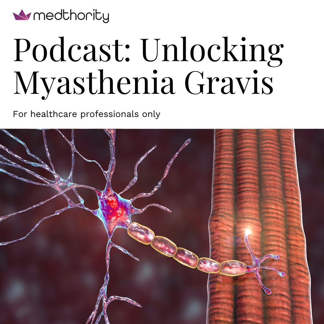
Catch up with latest episodes of the Unlocking Myasthenia Gravis (MG) podcast. Listen to Nils Erik Gilhus, Henry Kaminski, John Vissing, and Gil Wolfe discuss what patients often leave unsaid in clinic, when to consider thymectomy, and how new tools may shape future MG care
Starting with one of the most fundamental laws of electricity -
Ohm’s Law ⚡
It explains how voltage, current, and resistance are connected inside an electric circuit.
In simple words, the current flowing through a conductor depends directly on the voltage applied across it and inversely on its resistance.
This law forms the basic foundation of circuit analysis, electronics, electrical engineering, and modern technology. From household appliances to advanced electronic devices, Ohm’s Law plays an important role everywhere.