A lot of you have offered to and asked how you can support the lathe build, and since this is all so new to me, I didn’t really know how to answer that and haven’t felt comfortable just straight up asking people for money or specific parts. So after getting some suggestions and input from others, I finally set up something I feel comfortable with. No pressure at all, following along and sharing the build honestly helps just as much.
To be clear, I’m completely okay with funding this entire thing myself, I just can’t make any real promises on when it would be done. As the design grew into v2, the parts list grew with it and ended up costing way more than I originally intended. I’m a college student paying my own way through school, so I’ve been covering what I can with my own money and by returning parts I no longer need, and any help keeps me on track to have it running and cutting by this spring semester.
If you’re interested in supporting the build along the way, I started a Patreon at https://t.co/TjFL2taU07. Tiers start at $5 and range from your name in the credits of the open source release up to the in-depth engineering behind every decision (the calcs, the FEA and why each part ended up the way it did), early access to the CAD before it goes public, and a monthly Q&A. The first 30 founding members also get their name on a founders plate on the lathe and a custom stainless steel ring made on it once it’s cutting.
If you’d rather do a one-time thing, X Money works right from my profile, or Venmo (Vinnymace). And if you’d rather talk privately or want to help with a specific part, feel free to DM me.
Everything goes open source once it’s proven, so the CAD stays free no matter what, and nothing changes about the updates here on X. Patreon just gets the extra niche technical stuff like the actual FEA reports and calcs. I love showing anyone and everyone interested the build and progress on here, so none of that is going anywhere. The card below shows exactly where the money goes.
Huge thank you to the anonymous supporter who sent the first bit through X Money, to Clay (@SCH_Clay) for the servo, and of course @sendcutsend, thank you guys for being the first to back the project. Never expected any of this from what started as a passion project.
Feel free to drop any questions or concerns under this post. I’d really like feedback, especially on the Patreon side, since I had no idea what should be included in the tiers or what they should cost. I want this project to be for everyone, hence the decision to go fully open source, so don’t hesitate to give suggestions on how I could approach this better for everyone who’s graciously decided to follow along.
Sorry for the later reply, been caught up with a bunch of stuff but saw your mini lathe project, which I love, much less hard on the wallet than mine lmao. But I wanted to come back and answer because I remembered briefly seeing this comment. I went with a US Digital S5, 1000 lines with an index pulse, belted 1:1 off the back of the spindle with GT2 pulleys so the bore stays open for bar stock. Not sure what kinda targets you're trying to hit with yours but from what I've read about the S5 it should be able to cover your project perfect, also considered the E6B2 but ended up wanting something higher resolution when the spindle change became final. Would love to talk more in DMs if you're down
I’ve finally caught up on almost everything from the last 24 or so hours, so here’s the full breakdown of the lathe I promised, plus some big news on where it’s headed. First, a huge thank you to @sendcutsend for sponsoring the project, to @SCH_Clay for the shout that started all of this and for covering a new servo for the spindle, and to everyone who’s offered parts, machining help, advice and support. I went from 15 followers to a lot over 1000x that in less than a day, still blown away.
First thing I wanted to say is that It’s going open source
I’m officially going to open source this once it’s done and proven out. I’ll publish everything for every version, the CAD, drawings, BOMs with costs, build notes and machine settings, so anyone can build one. There are going to be three versions.
v0.5 is the cheapest way in. It’s a 24" bed with a 3/4 HP three phase motor on a VFD off a regular 120V outlet, running grbl on an Arduino Mega with NEMA 17s.
v1 is the same frame and spindle with grblHAL on a Teensy 4.1 and closed loop NEMA 23s.
v2 is the one I’m building since I have gotten the SCS sponsorship, the help from Clay, and a few other things and I cannot express enough how much I appreciate that support. It takes everything I learned designing v1 and everything from your replies, with a servo spindle, a longer bed, a stiffer Z axis, swappable gang tooling and real chip handling. Most of this post is about v2.
This fall I started training on the lathes in the machine shop at school where I work, fell in love with the lathes, and wanted a CNC lathe of my own I could use to make parts for my other projects. Before designing anything I priced out the mini lathes and what it would take to convert one. A converted 7x12 came out costing as much as building my own or more, the ones in my original budget have about 2" of swing over the cross slide and not much spindle torque, and nobody sells a ready made CNC conversion kit for them anymore. So I decided to design my own, which felt was a more worthwhile endeavor anyway.
The requirement I originally designed to is mild steel at 0.050" off the diameter in one pass (0.025" depth of cut) and light cuts in stainless. Almost every decision on the machine came from working out the stiffness and motor torque needed to hit that.
v0.5 and v1 are fully designed in SolidWorks, over 120 parts, and I’m actively redesigning the parts that change for v2 now. The build started at the end of October. It is not running or cutting yet. The first parts I’ve machined are the tram blocks, the push screw blocks that let me square the headstock to the Z axis. I'm looking to have most of the machining done by winter break so I can actually get to building it, and the goal is to have it cutting by the middle of the spring semester, ideally ironed out before the summer if I can. Really going to try and hold myself to this but I do have limitations given most of the work will be done in my school's shop.
Before locking in v2 I ran a full limitations study on v1, every axis, the structure, heat and accuracy, to find what would actually hold it back. v2 fixes most of what it turned up.
The base is an 8x4" steel rectangular tube with a 1/4" wall, bolted together with no welds since I'm kinda shit at welding lmao. On v2 it’s 27" long instead of 24", which buys a lot more Z travel. Across the top is a self leveling epoxy pour, and the top of that pour is the plane the linear rails and the headstock both sit on, so they come out coplanar without having to machine a bed.
Specifically to address the question from someone, the headstock is a bought Sieg C2 mini lathe casting with an upgraded spindle that takes a 4" chuck. I picked the C2 because it was the only headstock I could find with real drawings to design around, and buying a bored and finished spindle housing saves a lot of precision work that would've ate up a massive amount of time and money. I’m swapping the stock deep groove bearings for a preloaded pair of 7206 angular contact bearings, which drop into the same bores. The casting sits on a 3/4" steel T shaped spreader plate bolted across the tube, it’s located by a V key strip, and the tram blocks push it square to the Z axis. I stripped and measured the casting this week and to make sure the cheap chinese casting was accurate to the drawings and my CAD model.
As for the axis, Z rides on two 20 mm profile rails with four carriages. On v2 the rails are longer and shifted toward the tail end, which takes Z travel from about 6.8" to about 11". The Z ballscrew is the first thing that chatters on v1, so v2 goes to a bigger preloaded double nut ballscrew with heavier end supports and a gusseted nut bracket. X is a cross slide on two MGN12 rails with two blocks per rail on a 12 mm ballscrew. When I added up every joint between the tool and the bed, the cross slide on one block per rail let the tool shift about 30 microns under a full cut, and going to two blocks per rail took that to about 2. On v2 I’m also moving the X screw’s fixed bearing to the inner end, which cuts how much the diameter drifts as things begin to warm up by about 14 times, and a slightly longer X screw takes X travel from about 4.5" to a little over 5" so a rear row of tools can reach anything the chuck can hold
For everyone who asked about the motor and such, the original plan, and what v0.5 and v1 still use, was a 3/4 HP three phase motor on a VFD off a regular 120V outlet, belted to the spindle. That motor was one of the main limits on the machine. At carbide speeds it ran out of power before the rest of the machine did, it needed belt changes to get torque down low, and on a stop the chuck would coast for a long time. @SCH_Clay graciously helped obtain a servo, and after a lot discussion and input v2 gets a 1.5 kW AC servo on a 2 to 1 toothed belt. Which is basically the BLDC plus FOC setup a few people suggested, just in a kit that’s rated for continuous use. Through the belt that’s almost 10 Nm at the spindle all the time and almost 30 Nm in bursts, with full torque from zero rpm and a electronically braked stop instead of the chuck coasting. The mount takes other pulley pairs too, so I can go to 2.5 to 1 for more torque on bigger stock or 1.5 to 1 for more speed. Since I only readily have access to 120v it runs off a step up transformer, which caps it under 1 kW of continuous cutting power. And for safety, the spindle is capped at 2500 rpm until it has a proper enclosure.
For those who have asked the controls questions, v0.5 runs grbl on an Arduino Mega with NEMA 17s I already had, to get it moving fast. v1 and v2 run grblHAL on a Teensy 4.1 with closed loop NEMA 23s. For threading, there will be an encoder belted to the back of the spindle so grblHAL knows exactly where the spindel is and can do proper threading, since the Z axis has to move in step with the spindle. To be straightforward, this part is my biggest knowledge gap on this whole project, so I’m learning as I go with this and have been taking a lot of advice and guidance from several people more knowledgeable on this aspect. With that said I’m planning to run to a finer encoder so it tracks better at low speeds rather than just using the servo's built in one, and I'd like to get constant surface speed working for facing as again suggested by Clay.
For tooling, it uses gang tooling with 12 mm shank tools, so there’s no turret or tool changer. On v0.5 and v1 the tools sit in a basic gang block setup so you can swap them out for the task/job at hand in the moment but this leaves the issue of them losing their offsets and having to readjust said offsets when changing the tools almost every time. For v2 I’m making the blocks easier to swap so any tool can go in any slot at any time, a turning tool up front to get right up to the chuck, a parting tool or boring bar behind it, or a drill on center. I’m taking a lot inspiration from and looking at how production gang lathes handle quick change tooling so a block can come off and go back on without losing its offsets and of course welcome any advice or recommendations on how to improve upon this or where it could go wrong.
For the many people asking about how I'm dealing with chips and evac of them, on v0.5 and v1 it’s a flat deck with a removable cover over the Z screw and rails, a chip wall on the X and a chuck guard. That’s fine for proving it out on small cuts, but it won’t hold up long term. Based on the suggestions, all models around got to get bellows over the rails and screws, covers over the X rails and screw, and for v2 it'll get a chip tray the whole machine sits in and bolts through, so chips land somewhere I can just dump out. A slant bed is on the list for a potential future version as that becomes something that would either be too expensive or unrealistic to do in a reasonable amount of time given my constraints with being in school full time and doing this in my school shop.
When it comes to how its getting made, most of it will be done by me on 2 and 3-axis mills with some manual lathe work in the shop at school where I work to keep it simple and replicable. Laser cut and CNC machined flat parts come from @sendcutsend, the control panel is set to be 3D printed, and the deck is the epoxy pour I had mentioned.
As to the capabilities and where it'll actually be limited; going by my models, v1 should rough mild steel at around 0.020" to 0.030" depth of cut, with the Z ballscrew as the first thing to chatter. With the stiffer Z and the servo, v2 should more than double that to around 0.060" in mild steel on a 1" bar, which is 0.120" off the diameter in one pass. Stainless is harder to call because my models are somewhat sensitive and kinda swing back and forth because of the frequency the X axis vibrates at and the model freaks tf when that gets too close to the spindle's freq, but it should be somewhere in the ballpark of 0.020-0.030" but that still will have to be confirmed. At that point the limit in mild steel is how hard a 4" 3 jaw chuck can grip the part, not the machine. On a 120V outlet the deepest cuts have to run a bit slower than ideal carbide speeds, and on bigger stock the spindle torque sets the depth, which is what the 2.5 to 1 pulleys are for. It should hold around half a thou on diameter with a finish pass once it’s warmed up. There’s no tailstock yet, so work can only stick out about 2 times its diameter, and the longer bed leaves room to add one. Parting really has no limit besides how its positioned in the gang block/how much stickout it has. On accuracy, the things I’ll be fighting are X backlash and heat, so I’ll be re-touching off and warming it up before finish passes.
As to what's next, I'm going to be finishing the v2 design changes, working on getting the parts machined, sending off stuff to SCS, getting as much of the build put together over break, get it cutting in the spring, then tune it and get threading working. After that it's a tailstock, and further down the road maybe live tooling or a small mill add-on. Once it's cutting and proven out to my standards I'll publish all three versions with a full BOM and costs for each.
If anyone has more questions, drop them below and I'll happily keep answering. Thanks again everyone, this has been one of the most unreal 24hrs in my life 🙏
Obtained some incredible pieces of stock from my friend @genZmfg which I am incredibly grateful for, we got the 17-4 PH that will attempted, key work attempted to be used to make the tool blocks IF i can actually machine it in my schools shop lol. A big ole chunk of titanium, a rod of Inconel that I have no idea what to do with and some good ole 1018 steel which will likely be one of or the first piece of stock used to do tap tests and see how well my models hold up. Also some other useful goodies that'll be helpful throughout the build process, again thank you Ryan 🙏
Ayyy, first @noxmetals order for the lathe just came in, excited to finally get to actually cutting metal. I actually ordered this back before this project blew up for the v1 design and as I have mentioned, the design has changed massively since then so not all of it is going where it was originally intended lol. Got the cast plate for the carriage which luckily still fits, still using the 6061 foot flange pieces + end caps, and the big ole 4" round that was meant to be the spindle pulley is now being turned into the encoder drive cap/mounting enclosure but hey at least its getting used. Gonna end up using the rest for other random little bits and pieces, and some fixtures most likely so it ain't going to waste. Also honestly really cool they take the time to write hand written notes like this seemingly for every customer especially given the relatively small size and cost of this order. Really impressed with everything about this order and the process and simplicity of it. Massive kudos to the team over there at Nox
@dom_rocc0 Appreciate it, but yeah thats really what it comes down to with these older machines to get high quality results, literally all in the setup and the time you take to get it accurate. They're capable, just gotta be patient with em
This is a cool project, would be great for kids interested in engineering to get them exposure to accurate mechanisms and manufacturing. Interested to hear how you have Claude tied into whatever CAD package you use and what package it is, or are these STEP files and renders? Have tried a few harnesses to mess around with and could never get results I've been happy with so I've relegated Claude to purely analysis, still don't feel comfortable handing it design work. Curious to hear how you'll go about directing the models to make this truly functional or if you'll end up having to step in modeling wise, definitely is interesting to see how these models progress when it comes to mechanical design.
@CoxonMark Literally dude, I have "BUILD IT HERE" with an American flag in my banner and have gotten several Chinese shops/people asking if I want to order parts from them. The answer is no, no I do not. I'm making my shit myself or having another American make it.
Yeah ya'll are lucky with metal pricing over there, steel pricing is insane here in the US right now. I'd also assume a good bit of that pricing comes from import tax/tariffs unfortunately. Kinda sucks since a majority of the parts left are steel and a lot need to be stainless, high carbon or tooling steel
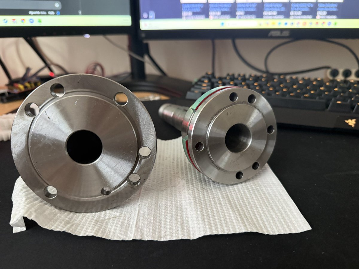
One on the right came with the headstock which in total was about $130 including shipping, and the one that got here today was $90 including shipping. Only spent the money on them because at the time, this project was intended to be way smaller and I didn't have access to equipment to make a headstock, and buying the steel stock to make one of the spindles probably would've cost me cost me close to the same, if not more given stainless prices in the US right now so I figured they'd be good enough with some grinding done. Like I literally get quoted between $120 and $200 for the A500 steel square tube stock I'm using as the base from any suppliers in my area and it would cost more to have one shipped. Steel pricing is insane
Honestly dont know how this one passed QC, it looked great when I initially got it, probably because I was just excited it finally got here but if you look closely, there are some relatively deep gashes with burs, the bolt holes literally have noticeable burs as well, plus this was clearly dropped and has that slight dent and raised surface. Little dissapointing ngl but tbf this is intended for a shitty manual Cieg mini lathe, they're probably pumped out by the thousands in some Chinese shop with people working 12-16 hour shifts for $10
@Takii_ovo but tbf, theyre not bad for what they cost, really could probably get away with grinding it one a surfacing stone but I have better tools at my disposal now so might as well use them to make sure its pretty much perfect
Not 100% sure, they were obviously turned on a lathe but I didn't make them, these were ordered. Going to take them to my buddy's shop to check em and get a proper model for them with his CMM and machine the one I'm using pretty much as perfect as I possibly can. The new one has a visually noticeable drop mark that raised a part of the surface the slightest bit which will throw off the chuck enough to where it'll be out of my tolerance goals so gotta fix that.