@ryzerth@JamesMcPherson UHDI, more of stacked chips (SoC) with clever package design and pinout. Decrease losses in the interfaces to increase bandwidth and decrease power consumption.
@i2cjak The bottleneck might be the PDM microphone data transfer rather than the microcontroller. Approx 3 MHz clock to split on data and sample rate. Might also have to split the bandwidth in 2 for FB and FF if using only one PDM.
@minusYCore@blind_via It depends on the board stackup. Closely spaced power and ground, then go for via in pad. Widely spaced planes, or ground plane with routed power, then via-cap-pin.
For via pairs, the distance between them matters more than their diameter.
@ahmad_builds@blind_via Another thing to consider is also the impedances vs stackup. It might be better, from a manufacturing standpoint, to group similar impedance(s) on the same layer(s). Easier to optimize and to achieve the target impedances with a good yield.
@ahmad_builds@blind_via Yes. The E-field between the trace and the reference plane(s) spreads out a bit, so ideally those spreads should not overlap to minimize cross talk. Google 3W-rule
Copper pour also matters. Could change trace impedance model between stripline & coplanar if clearance is too small
@blind_via I think it was @QVHenkel who wrote a good summary of the HW design feedback loop issue. What was the motivation for design changes between revisions? Sourcing, mechanical, EMC, functional, scope change? The quality, or lack of, such data is a problem for AI training.
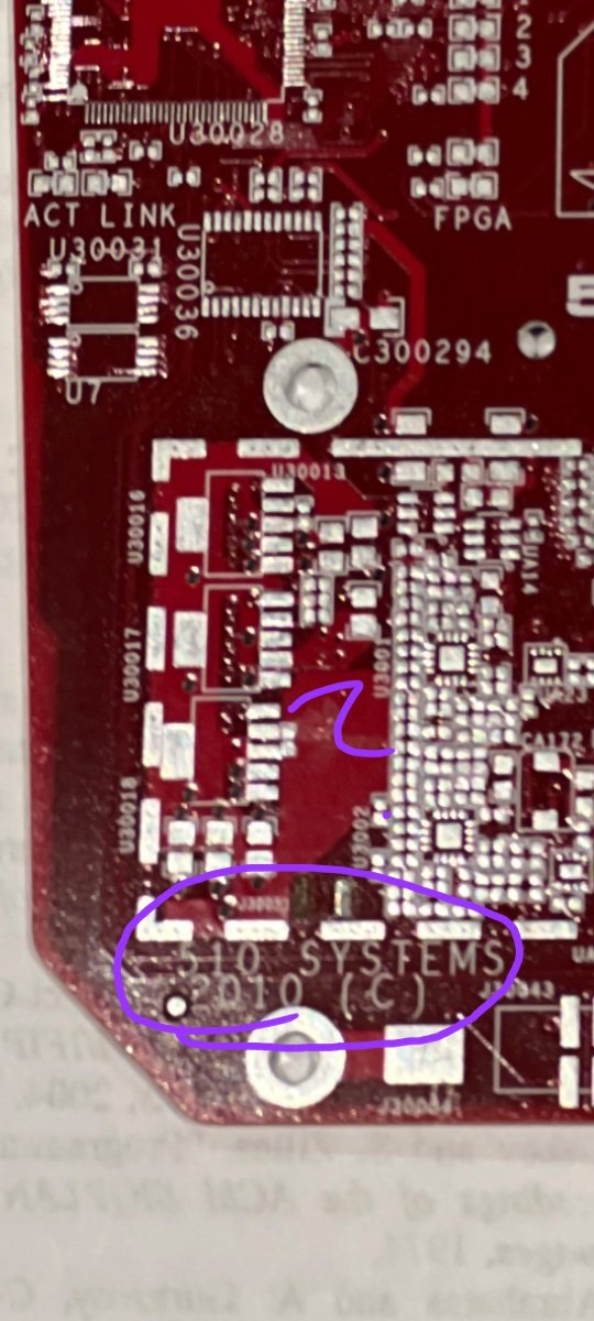
@MuzafferKal_@blind_via And what does this exact board, dated 2010, have to say about AI assisted routing? I see the shape, but apart from that I doubt it will add anything to the topic.
@kleschby@ryzerth Not really. Design rule check could help with some, if configured, but that is typically not the case. The default settings are more focused on manufacturing capabilities, like trace width and insulation distances.
First thing to check: the stackup
@raulizahi Thanks! Did not really make sense to calculate eye patterns for a 2 layer board based on the top and bottom views in the other post. Also the dielectric thickness would be "a bit" thick...
@lagz152507 There are 2 clues in the picture. The heat sink and the white thermal grease. Both are indicators of possibly higher ambient temperature, which is not good for the expected life time. Lower the temp by 10'C and you get twice the life time. Do it again, and get 2x more...
@RaymingTech Absolutely terrible stackup!
Who would put the supply plane as reference plane for the top layer? First inner layer should be 0V/GND. Then place the supply below that so it also references the same plane as the top layer, but not for 4 layers, only for 6 layers or more.
@animeshsingh38@cmonkey@copperheadhq Layout
What I have not seen any of the AI tools show yet is a layout strategy that is field aware. Not just connect the dots-spaghetti on 2 or 4 layers.
@animeshsingh38@cmonkey@copperheadhq Workflow
Requirements with tracking, design rules, tracking of changes - by whom and when?, diff between revisions.
@animeshsingh38@cmonkey@copperheadhq Schematics
Hierarchy to get overview and details. The "all on one sheet" with connect by name is useless to check signal flow.
Symbol arrangement, as I commented earlier. GND points down and is not flipped over.
Opamp supply, why is the negative supply point up?
Comment/Notes
@animeshsingh38@cmonkey Yes, I have noticed that and also that the schematics samples looked less optimal. For professional use, just that something is open source is not necessarily a must and could have zero benefit. Things like documented work flows, traceability etc matters more.
@animeshsingh38@cmonkey It's always this talk about the next release as an excuse. Why should we even look at something if it still is early-alpha-prototype-preview...?
@copperheadhq It's not about open source, it is more of a technical nature.
Let's make a battery powered headphone that is used by a patient during an MRI scan. What would the prompt(s) be and what is the result?
Also how are design updates documented with respect to MDR and FDA?
@copperheadhq Let's see. There is a lot of teasing about next release from almost everyone, but still no one seems to deliver anything useful for levels above "hobbyist". As a reference I worked in automotive earlier and now in medical.