Spent 30 minutes trying to debug my circuit only to find that the mfr datasheet for the MOSFET I was using was wrong and had the gate and drain reversed
Just got a @BambulabGlobal Carbon X1 and wow, just wow. It just works. No fiddling, no software compiling, no tweaking. Super fast. I haven't tried a multi-color print with the AMS yet but that's coming soon
Some species of anteaters like the Gaint Anteater appear as if they have two or three heads. However, this illusion is created by their black and white furry paws which give the appearance that their front limb is the head
Building a new stainless steel grate for my offset smoker. I made a modified box joint jig for spacing and cut 5/16 stainless round bar to fit, then TIG welded everything up
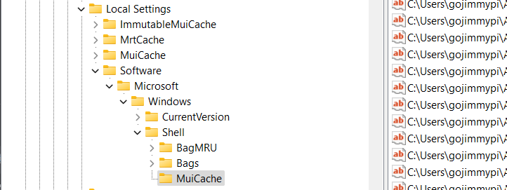
TIL about HKEY_USERS\Software\Classes\Local Settings #MuiCache
A history of executables that ran on Windows.
It's apparently been a feature for over a decade.
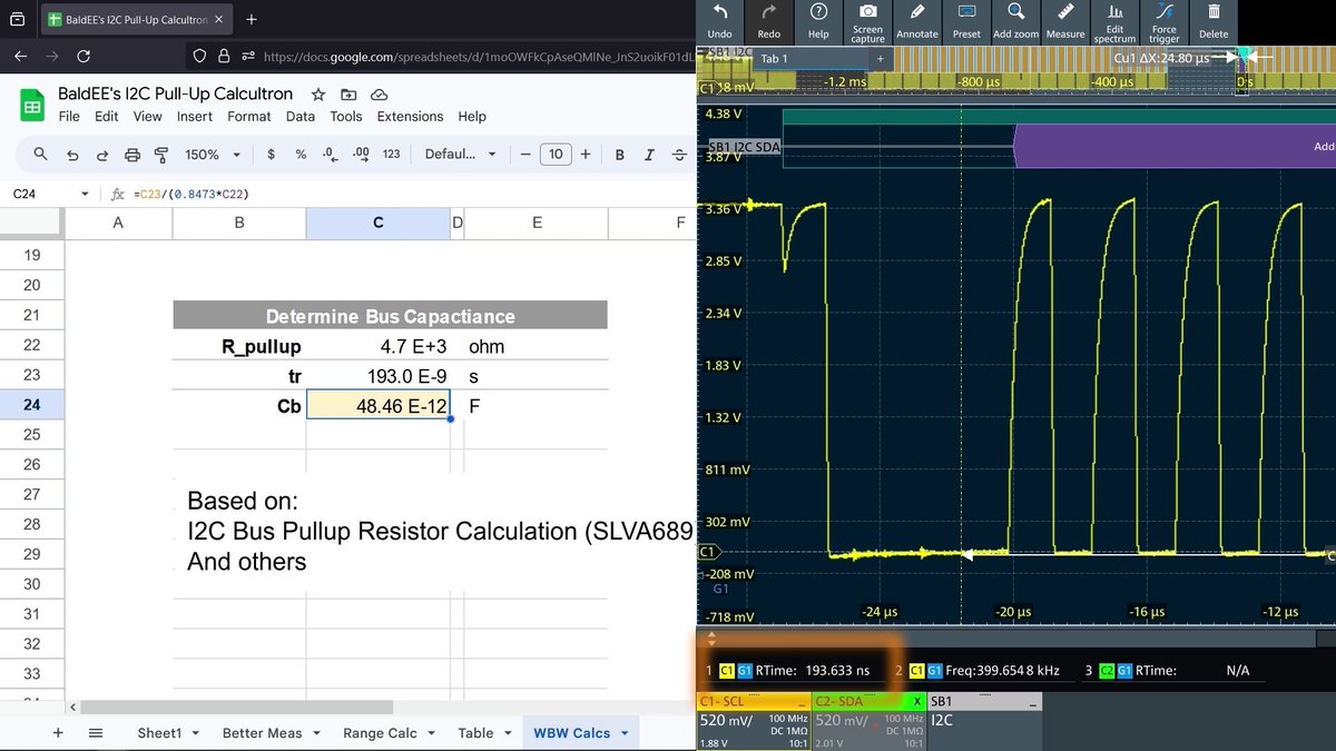
Calculating I2C Pull-Up resistors requires knowing the bus capacitance. Here's why AND what to do when you don't know that value. (Spoiler: Use an oscilloscope to measure/verify it.)
My #ZigBee2MQTT just got better and you can add this little life-quality improvement too! Check out what I found in the latest #Z2M installation and how it can make your day better!
#net_r#homeautomation
https://t.co/BWl1eBqsPC
Preview - Work has begun on the new guide. Finally. This year has been unbelievably stressful in my personal life, and so much has happened. Most of the worse I think is almost done. Going to try to come back to what I love now. Helping people.
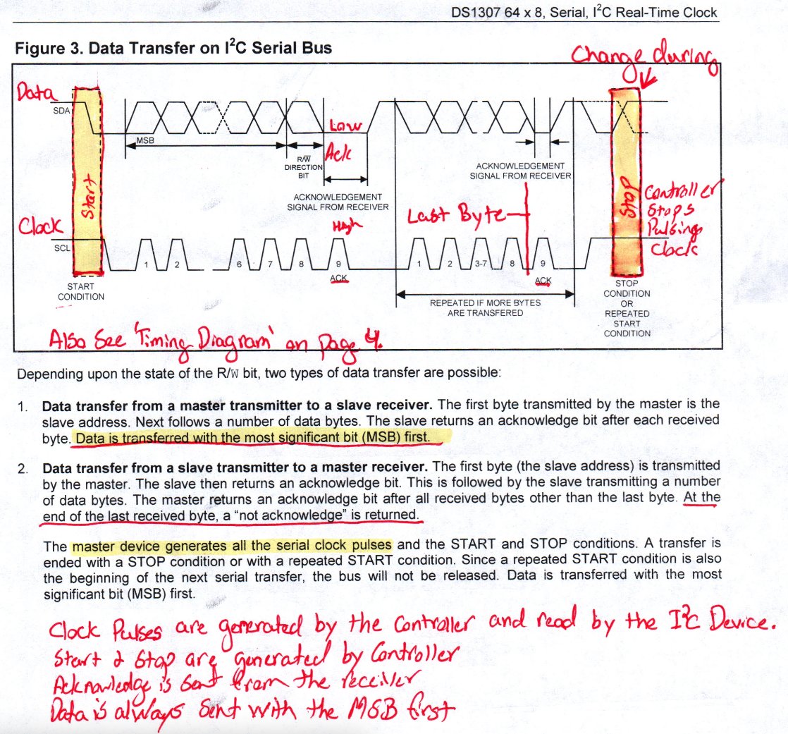
The I2C Protocol According to the DS1307 Datasheet
Buckle Up – You’re going on a crash course in I2C Data Communication according to the DS1307 Datasheet.
Some things to go over before starting.
I2C uses two connections for communication. It has a Data pin, called SDA, and Clock Pin, called SCL.
The controller is the I2C device that generates the clock signal. I2C devices on the bus do not generate their own clock signal. An I2C device can not initiate I2C communication with the controller on it’s own.
On page 6, you can read that the I2C Pins are Open Drain, meaning that they need a pull-up resistor. The device manipulates the signal by pulling it low, but in a resting state it is logic high, because it is pulled up.
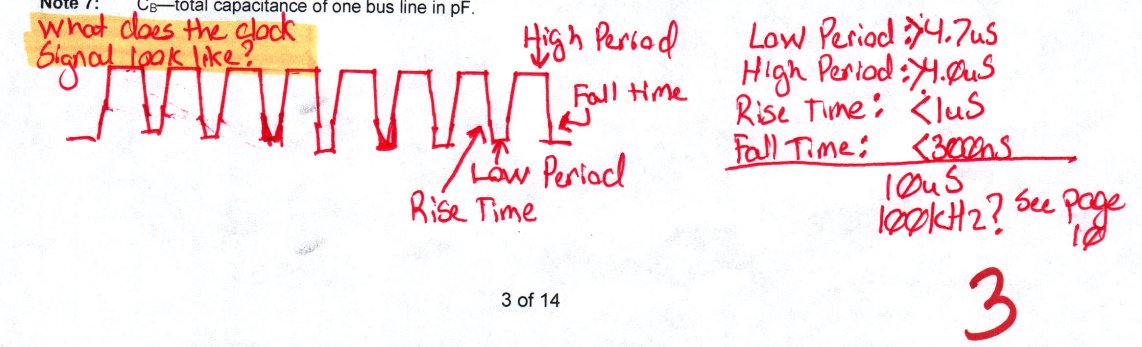
Going back even further to Page 3, where we find the AC Electrical Characteristics, it describes the clock signal and shows a complete cycle adding up to 10uS.
Page 10 starts by introducing the control signals. There are four main control signals that are used by manipulating the data line, during a high clock pulse.
I2C has four control signals It has:
- a not busy signal
- start signal
- stop signal
- and acknowledge signal.
The signal and data being transmitted is dictated by what position the data logic is in, but only while the clock pin is high. When the clock pin is not high, it doesn’t matter what the data pin is doing, until the controller sends the START signal.
Before communication starts, both the clock and data lines should be pulled high, because the I2C lines have a pull up resistor on them.
To start communications, the controller will change the data pin from high to low, while the clock signal is high. Again, within the period of time while the clock is high, which on page 3 we see that the high period is 4 uS, the data pin will change from a high state to a low state, which on page 3 again we see that the fall time for the data line is 0.3 uS.
This signals to every device on the I2C bus that we are about to start some I2C communication. Following this signal, the controller will send a 7-bit address that matches an I2C device on the bus. The eighth bit in the byte is a Read or Write command. This bit is high for reading data and it is low to tell the device that the controller is going to send data to write to its registers.
Following every byte sent, the I2C device will send an acknowledge bit. The acknowledge bit is when the receiving device pulls the data pin low on the clock pulse following each byte.
This is how every I2C communication starts.
Following this, the controller or device will send bytes to each other and they would send ack signals to each other.
When communication is over, the controller will send a STOP signal. When the controller wants to send a STOP signal, it will let the data pin go from low to high during the clocks high period. On page 3 we see that the rise time is 1 uS.
That covers all of the control signals. There is also something called ‘Repeated Start’, but that’s used to write and we’ll go over that later. Everything else on the I2C bus is addresses with R/W bits or byes of data, parsed by acknowledge bits sent from the receiving device.
Continuing down page 10, The datasheet tells us that the I2C bus can operate at a standard mode of 100 khz or fast mode of 400 khz, but the DS1307 only operates at 100kHz, which is a cycle length of 10 uS, which we can confirm on Page 3.
Flipping to page 11, we’re presented with Figure 3. It shows a good example of what the data and clock lines look like. You should check it out.
Okay, before we start page 12, let’s do a quick review:
- Clock Pulses are generated by the controller, not the device.
- Start and Stop signals are generated by the controller.
- The Ack bit it always sent from the receiver and sent after every byte of information.
- Data is always sent with the Most Significant Bit First.
- When reading from a device, the device will read from where the pointer is or from the beginning.
Page 12 and 13 show the three communication protocols within the I2C standard. There is:
- Data Write – Where the controller write data to the device.
- Data Read – Where the device sends data to the controller starting from where the register pointer is.
- Write Pointer Data Read – Where the controller points to an address and then reads from there.
Let’s go over them.
Data write goes like this:
- The controller sent the start signal, a 7-bit address, followed by a 0, which tells every device on the I2C bus what address you want to start communication with and that you want to write to it.
- The device sends an acknowledge bit, which is pulling the data line low on the following clock pulse.
- This is followed by the register address you want to start writing to
- This is again followed by an acknowledge bit from the device.
- Then the controller sends bytes of data followed by an acknowledge bit. It keeps writing bytes until it’s finished.
- When it’s finished, the controller send a stop signal.
- Both lines return to a NOT BUSY condition with both lines pulled high.
Something to remember from Page 7, if you’re writing and you write past address 3Fh, it will wrap around to register 00h and it will overwrite your clock data.
Data read goes like this:
- The controller send the start signal, followed by the device’s 7-bit address and a 1 bit.
- The device sends an acknowledges bit
- Then the device sends the first byte of data.
- The controller then sends the acknowledge bit following each byte the device sends.
- When the controller is finished reading, the controller send a high bit instead of a low bit on the following clock pulse and then sends the stop signal.
Something about Data read to remember is that it will start reading where ever the register pointer is when the read command is sent. Also, the device will continue to send you data until you tell it to stop by sending the stop signal.
To tell the device what register you want to start reading from, you need to do whats called a ‘Write Pointer Data Read’. To do this we tell the device we want to write to it, then what address we want to start writing to, and then we send another start signal, followed by the address and the read bit, then start reading.
It goes like this:
- The controller sends the start signal, followed by the 7-bit device address and a low write bit.
- The device sends the acknowledge signal.
- The controller sends the register address that it wants to write to
- The device sends and acknowledge and the register pointer has moved.
- Now the controller sends another start signal, followed by the same 7-bit address from before, but now with a high read bit.
- The device sends and acknowledge bit, then reads out the first byte
- And then the controller sends acknowledge signals until it’s finished.
- When the controller is finished, it will send a high not acknowledge bit followed by the STOP signal.
You will almost always read data in your firmware in this way because it moves the register pointer where you want it to be when you start.
That covers the I2C Protocol, according to the DS1307 Datasheet. This datasheet can be found from https://t.co/NpU1wxrQxX
If you liked this, you’d probably like my podcast. Here is a link to the DS1307 episode. Available on Spotify, Apple Podcasts, Amazon Music, Audible and more. https://t.co/MqT0OdJ28x
Thank you for your time and have a great day.
Don't waste time and money on video editing.
ChatGPT is now capable of creating a complete video.
Here's exactly how to do it using just one plugin on ChatGPT: